Mitsubishi Lancer Evolution 7. Manual - part 222


  Index      Mitsubishi     Mitsubishi Lancer Evolution 7 - service repair manual


Search            


Content   ..  220  221  222  223   ..


Mitsubishi Lancer Evolution 7. Manual - part 222


INTAKE AND EXHAUST -

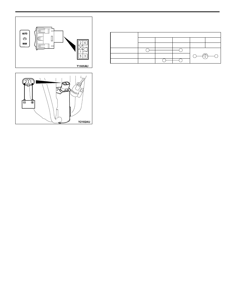
Intercooler Water Spray

ILL

15-13

INSPECTION

1. WATER SPRAY SWITCH CONTINUITY CHECK

Switch position Terminal No

Switch position Terminal No.

p

AUTO

MANUAL EARTH

ILL (+)

ILL (-)

1

2

3

5

6

AUTO
NEUTRAL
MAN

2. WATER SPRAY MOTOR CHECK
(1) Check the water spray motor with the washer tank

attached after the washer tank is supplied with water.

(2) Check that the water is supplied with strong pressure

after energizing terminal number 1 with battery voltage

and earthing terminal number 2.

<Water spray switch>

<Water spray motor>

INTAKE AND EXHAUST -

Secondary Air Supply System

15-14

SECONDARY AIR SUPPLY SYSTEM

REMOVAL AND INSTALLATION

Pre-removal and Post-installation Operation
D

Air Duct Removal and Installation (Refer to P.15-8.)

D

Strut Tower Bar Removal and Installation (Refer to GROUP 42.)

1

2

3

4

5

49 ± 5 N·m

14 ± 1 N·m

22 ± 4 N·m

14 ± 1 N·m

14 ± 1 N·m

20 ± 2 N·m

6

8

9

10

22 ± 4 N·m

24 ± 3 N·m

23 ± 4 N·m

11 ± 1 N·m

Air pipe C

5.9 ± 1.0 N·m

7

7

11

Removal steps

1. Control harness connector

connection

2. Heat protector

3. Vacuum hose connection

D

Air pipe C (Refer to P.15-9.)

4. Vacuum pipe

5. Secondary air hose

6. Secondary air pipe assembly

"

AA 7. Gasket

"

BA 8. Gasket

9. Secondary air control valve

10. Engine hanger

11. Secondary air control valve bracket

INTAKE AND EXHAUST -

Secondary Air Supply System

15-15

INSTALLATION SERVICE POINTS

"

AGASKET INSTALLATION

Install the gasket so that its salient can face towards the

direction as shown in the illustration.

"

BGASKET INSTALLATION

Install the gasket so that its protrusion can face towards the

direction as shown in the illustration.

Salient

Secondary air pipe assembly

Protrusion

INTAKE AND EXHAUST -

Intake Manifold

15-16

INTAKE MANIFOLD

REMOVAL AND INSTALLATION

Pre-removal and Post-installation Operation
D

Air Duct Removal and Installation (Refer to P.15-8.)

D

Strut Tower Bar Removal and Installation

(Refer to GROUP 42.)

D

Under Cover Removal and Installation

(Refer to GROUP 51 - Front Bumper.)

D

Engine Coolant Draining and Supplying

(Refer to GROUP 14 - On-vehicle Service.)

D

Throttle Body Removal and Installation (Refer to

GROUP 13A - Throttle Body.)

D

Crossmember Bar Removal and Installation (Refer

to GROUP 32 - Engine Roll Stopper, Centermember.)

D

Front Exhaust Pipe Removal and Installation (Refer

to GROUP 15 - Exhaust Pipe and Main Muffler.)

D

Secondary Air Control Valve Bracket Removal and

Installation (Refer to P.15-14.)

D

Engine Oil Draining and Supplying

1

2

3

4

5

6

7

8

10

11

12

14

13

15

16

17

18

9

11 ± 1 N·m

3.0 ± 0.5 N·m

13 ± 1 N·m

(Engine oil)

(Engine oil)

5.0 ± 1.0 N·m

14

8

Removal steps

1. Center cover

2. Oxygen sensor connector

connection

3. Injector connector connection

4. Fuel pressure solenoid valve

connector connection

5. Purge control solenoid valve

connector connection

6. Knock sensor connector connection

7. Vacuum hose connection

8. Vacuum hose

9. Fuel return hose connection

"

AA 10. Fuel high-pressure hose connection

11. O-ring

A

A"

12. Delivery pipe, Injector and fuel

pressure regulator assembly

13. Insulator

14. Insulator

15. Oil level gauge and guide

16. O-ring

17. Brake booster vacuum hose

connection

18. Purge hose connection


Content   ..  220  221  222  223   ..