Mitsubishi Lancer Evolution 7. Manual - part 210
MPI -
On-vehicle Service
13A-139
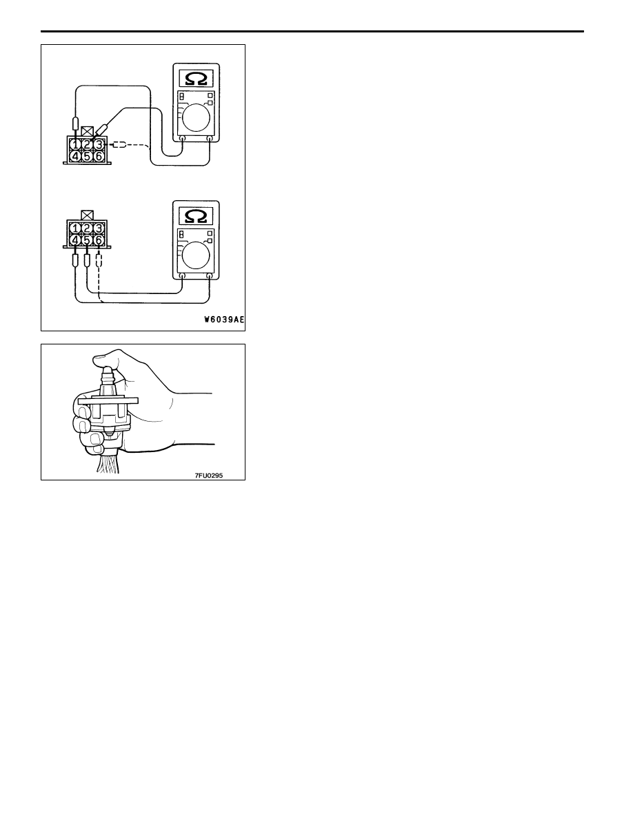
Checking the Coil Resistance
1. Disconnect the idle speed control servo connector.
2. Measure the resistance between terminal No. 2 and either
terminal No. 1 or terminal No. 3 of the connector at the
idle speed control servo side.
Standard value: 28 - 33 Ω (at 20_C)
3. Measure the resistance between terminal No. 5 and either
terminal No. 6 or terminal No. 4 of the connector at the
idle speed control servo side.
Standard value: 28 - 33 Ω (at 20_C)
Operation Check
1. Remove the throttle body.
2. Remove the stepper motor.
3. Connect the special tool (test harness: MB991709) to
the idle speed control servo connector.
4. Connect the positive (+) terminal of a power supply
(approximately 6 V) to the terminals No. 2 and No. 5.
5. With the idle speed control servo as shown in the
illustration, connect the negative (-) terminal of the power
supply to each clip as described in the following steps,
and check whether or not a vibrating feeling (a feeling
of very slight vibration of the stepper motor) is generated
as a result of the activation of the stepper motor.
(1) Connect the negative (-) terminal of the power supply
to the terminals No. 1 and No. 4.
(2) Connect the negative (-) terminal of the power supply
to the terminals No. 3 and No. 4.
(3) Connect the negative (-) terminal of the power supply
to the terminals No. 3 and No. 6.
(4) Connect the negative (-) terminal of the power supply
to the terminals No. 1 and No. 6
(5) Connect the negative (-) terminal of the power supply
to the terminals No. 1 and No. 4.
(6) Repeat the tests in sequence from (5) to (1).
6. If, as a result of these tests, vibration is detected, the
stepper motor can be considered to be normal.