Mitsubishi Lancer Evolution 7. Manual - part 211
MPI -
Throttle Body
13A-143
THROTTLE BODY
REMOVAL AND INSTALLATION
Pre-removal and Post-installation Operation
D
Under Cover Removal and Installation
(Refer to GROUP 51 - Front Bumper.)
D
Engine Coolant Draining and Supplying
(Refer to GROUP 14 - On-vehicle Service.)
D
Strut Tower Bar Removal and Installation
(Refer to GROUP 42.)
D
Air Hose E, Air By-pass Hose, Air Pipe C Removal
and Installation (Refer to GROUP 15 - Intercooler.)
D
Accelerator Cable Adjustment (Refer to GROUP 17
- On-vehicle Service.) <Post-installation>
2
19 ± 3 N·m
5.0 ± 1.0 N·m
1
3
4
5
6
7
5
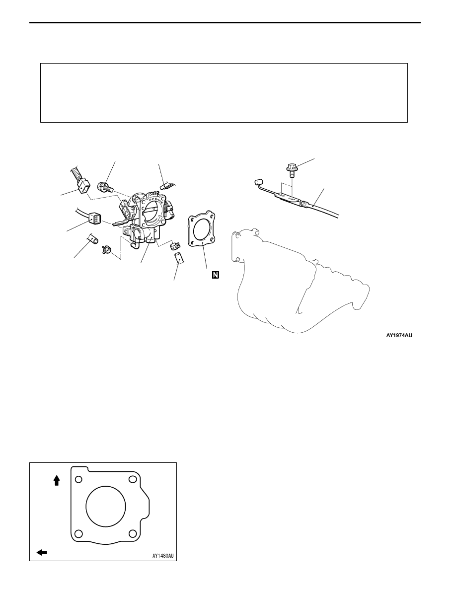
Removal steps
1. Accelerator cable connection
2. Throttle position sensor connector
3. Idle speed control servo connector
4. Vacuum hose connection
5. Water hose connection
6. Throttle body
"
AA 7. Throttle body gasket
INSTALLATION SERVICE POINT
"
AA THROTTLE BODY GASKET INSTALLATION
Place the gasket so that the projecting part is positioned
as shown in the illustration, and then install it between the
intake manifold and the throttle body.
Up
Towards front of vehicle