Mitsubishi Lancer Evolution 7. Manual - part 194


  Index      Mitsubishi     Mitsubishi Lancer Evolution 7 - service repair manual


Search            


Content   ..  192  193  194  195   ..


Mitsubishi Lancer Evolution 7. Manual - part 194


MPI -

Troubleshooting

13A-75

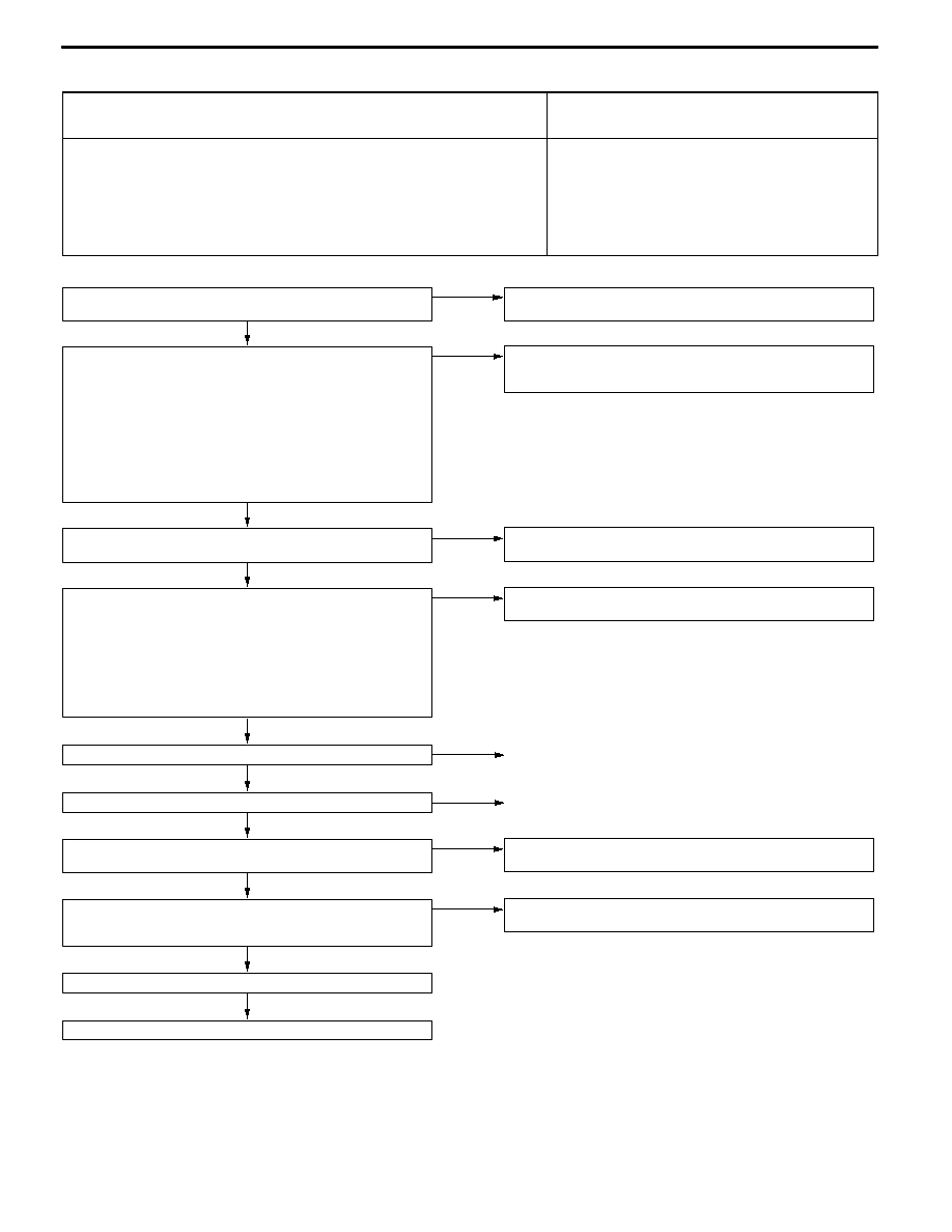
Inspection Procedure 17

Abnormal odor, white smoke, black smoke, high CO or HC

concentration when idling

Probable cause

Causes shown on right are suspected.

D

Air/fuel ratio control system malfunction

D

Ignition system malfunction

D

Fuel system malfunction

D

Intake and exhaust system malfunction

D

Exhaust gas purifier system malfunction

D

Improper compression pressure

D

Catalyst defect

D

Engine-ECU malfunction

OK

To the next page

OK

Check the fuel pressure. (Refer to P.13A-128.)

OK

MUT-II Data list
D

No. 59: Oxygen sensor (rear)

(Refer to P.13A-105.)

NG

Check the Code No. P0136: Oxygen sensor (rear) system.

(Refer to P.13A-27.)

OK

MUT-II Data list
D

No. 11: Oxygen sensor (front) (Refer to P.13A-102.)

NG

Check the Code No. P0130: Oxygen sensor (front) system.

(Refer to P.13A-24.)

OK

Check for exhaust gas leaks from exhaust manifold.

NG

Repair

OK

Check the air intake from the intake hose and intake manifold.

NG

Repair

OK

MUT-II Data list
D

No. 12: Air flow sensor

D

No. 13: Intake air temperature sensor

D

No. 21: Engien coolant temperature sensor

D

No. 25: Barometric pressure sensor

(Refer to P.13A-102.)

<Reference>

Proceed to OK if all service data values are correct.

Proceed to NG if there is even one abnormal service data value.

NG

Refer to inspections for diagnosis code of sensor showing

abnormal service data. (Refer to P.13A-102.)

OK

Check the ignition timing.

(Refer to GROUP 11 - Engine Adjustment.)

NG

Check the Inspection Procedure 15: Deviation of ignition interval

(Refer to P.13A-73.)

NO

MUT-II Actuator test
D

No. 01: No. 1 injector

D

No. 02: No. 2 injector

D

No. 03: No. 3 injector

D

No. 04: No. 4 injector

OK: The idling state changes.

D

Proceed to NG if the cylinder (NG cylinder) for which the idling

state did not change when injector was stopped is pinpointed.

D

Proceed to OK if all cylinders are OK, or if the NG cylinder

cannot be pinpointed.

NG

Check the Code No. P0201: No. 1 injector system, P0202: No. 2

injector system, P0203: No. 3 injector system and P0204: No. 4

injector system. (Refer to P.13A-30, 31, 32, 33.)

MUT-II Self-Diag code
D

Is a diagnosis code output?

YES

INSPECTION CHART FOR DIAGNOSIS CODE

(Refer to P.13A-12.)

MPI -

Troubleshooting

13A-76

NG

Replace the engine-ECU.

Check the trouble symptoms.

OK

End

NG

Replace the catalyst.

Check the trouble symptoms.

OK

End

OK

Replace the injectors for all cylinders.

OK

Check the compression pressure.

(Refer to GROUP 11 - Engine Adjustment.)

NG

Repair

OK

Check the ignition coil parts.

(Refer to GROUP 16 - Ignition Device.)

NG

Replace the ignition coil.

OK

Check the spark plug. (Refer to GROUP 16 - Ignition Device.)

NG

Replace the spark plug.

OK

Check the spark plug cable.

(Refer to GROUP 16 - Ignition Device.)

NG

Replace the spark plug cable.

OK

Check the PCV valve.

(Refer to GROUP 17 - Exhaust Gas Purifier Check.)

NG

Replace the PCV valve.

OK

Check the EGR valve for sticking.

(Refer to GROUP 17 - Exhaust Gas Purifier Check.)

NG

Replace the EGR valve.

OK

Check the EGR control solenoid valve.

(Refer to GROUP 17 - Exhaust Gas Purifier Check.)

NG

Replace the EGR control solenoid valve.

OK

Check the purge control solenoid valve.

(Refer to GROUP 17 - Exhaust Gas Purifier Check.)

NG

Replace the purge control solenoid valve.

From the previous page

MPI -

Troubleshooting

13A-77

Inspection Procedure 18

Battery dies

Probable cause

Causes shown on right are suspected.

D

Battery malfunction

D

G terminal short-circuit

D

Alternator malfunction

D

Engine-ECU malfunction

OK

To the next page

OK

Check the following connector:

C-122

NG

Repair

OK

Replace the alternator.

NG

OK

Check the harness between the

alternator and ignition switch.
D

Check for damage of the power

cable.

Repair

NG

OK

Check the harness between the

alternator intermediate connector and

alternator.
D

Check for disconnection and

short-circuit of the power cable.

Repair

NG

OK

Check the harness between the

alternator intermediate connector and

alternator.
D

Check for short-circuit of the output

cable.

Repair

OK

Measure at the B-14 alternator

intermediate connector.
D

Disconnect the connector to

measure at the male connector

side.

D

Ignition switch: ON

D

Voltage between terminal No. 10

and earth

OK: System voltage

NG

Check the following connector:

B-22

NG

Repair

OK

Check and repair the harness between

the alternator intermediate connector

and ignition switch.
D

Check for disconnection and

short-circuit of the power cable.

OK

Measure at the B-14 alternator

intermediate connector.
D

Disconnect the connector to

measure at the female connector

side.

D

Ignition switch: ON

D

Voltage between terminal No. 9 and

earth

OK: System voltage

NG

Check the following connectors:

C-130, C-01, C-213, C-29 <L.H.

drive vehicles>

NG

Repair

OK

Check the following connector:

B-14

NG

Repair

Check the battery.

(Refer to GROUP 54 - Battery.)

NG

Replace the battery.

MPI -

Troubleshooting

13A-78

NG

Replace the engine-ECU.

OK

Check the trouble symptoms.

OK

Intermittent malfunction

(Refer to GROUP 00 - Points to Note

for Intermittent Malfunctions.)

OK

Measure at the C-122 engine-ECU

connector.
D

Measure the engine-ECU terminal

voltage.

D

Engine: Idling (after warm-up)

D

Radiator fan: Stopped

D

Voltage between terminal No. 33

and earth

OK: Voltage rises 0.2 to 3.5 V

when headlamp is turned

OFF and ON.

NG

Check the charging device.

(Refer to GROUP 16 - Charging

Device.)

OK

Measure at the C-122 engine-ECU

connector.
D

Disconnect the connector to

measure at the harness side.

D

Ignition switch: ON

D

Voltage between terminal No. 33

and earth

OK: System voltage

NG

Check and repair the harness between

the alternator intermediate connector

and engine-ECU.
D

Check for short-circuit of output

cable.

From the previous page


Content   ..  192  193  194  195   ..