Mitsubishi Lancer Evolution 7. Manual - part 162


  Index      Mitsubishi     Mitsubishi Lancer Evolution 7 - service repair manual


Search            


Content   ..  160  161  162  163   ..


Mitsubishi Lancer Evolution 7. Manual - part 162


ENGINE OVERHAUL -

Timing Belt

11B-25

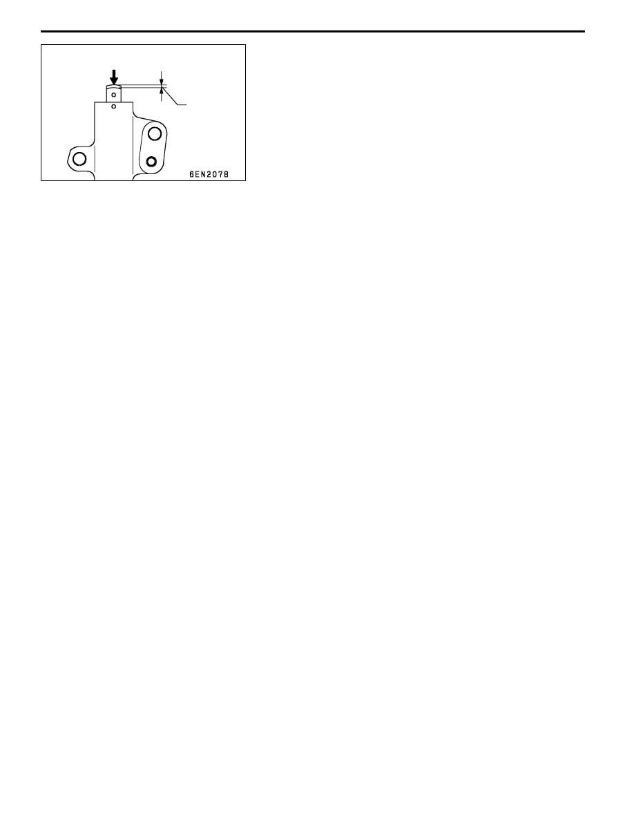
(4) Measure the depression amount when the rod is

pressed with a force of 98 to 196 N. If not at the

standard value, replace the auto tensioner.
Standard value: 1 mm or less

Depression

amount

98 - 196 N

ENGINE OVERHAUL -

Fuel System

11B-26

FUEL SYSTEM

REMOVAL AND INSTALLATION

1

11 ± 1 Nm

2

3

4

5

6

7

8

9

10

11

12

13

14

15

16

17

18

19

20

21

22

23

24

25

11 ± 1 Nm

20 ± 2 Nm

19 ± 3 Nm

± 1 Nm

8.8 ± 2.0 Nm

± 1 Nm

± 1 Nm

± 1 Nm

Removal steps

1. Throttle body assembly

"

CA 2. Throttle body gasket

3. EGR valve

4. EGR gasket

5. Fuel hose

"

BA 6. Fuel pressure regulator

7. O-ring

8. Delivery pipe and injector

9. Insulator

10. Fuel return pipe

11. Insulator

"

AA 12. Injector

13. O-ring

14. Grommet

15. Delivery pipe

16. Vacuum hose

17. Vacuum hose

18. Vacuum hose

19. Solenoid valve assembly

20. Solenoid valve assembly

21. Vacuum hose and pipe

22. Solenoid valve assembly

23. Vacuum tank bracket

24. Vacuum tank

25. Vacuum tank hose assembly

ENGINE OVERHAUL -

Fuel System

11B-27

INSTALLATION SERVICE POINTS

"

AINJECTOR INSTALLATION

1. Apply a small amount of new engine oil on the O-ring.

2. While rotating the injector to the left and right, insert the

O-ring into the delivery pipe while taking care not to

damage it.
Caution

Make sure that the engine oil does not enter the

delivery pipe.

3. Confirm that the injector rotates smoothly. If it does not

rotate smoothly, the O-ring may be biting in. Remove

the injector, check the O-ring for damage, and then insert

it into the delivery pipe. Check the rotation again.

"

BFUEL PRESSURE REGULATOR INSTALLATION

1. Apply a small amount of new engine oil on the O-ring.

2. While rotating the fuel pressure regulator to the left and

right, insert the O-ring into the delivery pipe while taking

care not to damage it.
Caution

Make sure that the engine oil does not enter the

delivery pipe.

3. Confirm that the fuel pressure regulator rotates smoothly.

If it does not rotate smoothly, the O-ring may be biting

in. Remove the fuel pressure regulator, check the O-ring

for damage, and then insert it into the delivery pipe. Check

the rotation again.

"

CTHROTTLE BODY GASKET INSTALLATION

Assembly so that the protrusion on the throttle body gasket

is at the position shown in the illustration.

Protrusion

ENGINE OVERHAUL -

Secondary Air System and Intake Manifold

11B-28

SECONDARY AIR SYSTEM AND INTAKE MANIFOLD

REMOVAL AND INSTALLATION

1

11 ± 1 Nm

2

3

4

5

6

7

8

9

10

11

12

13

11 ± 1 Nm

24 ± 3 Nm

14 ± 1 Nm

31 ± 3 Nm

± 1 Nm

20 ± 2 Nm

22 ± 4 Nm

36 ± 6 Nm

23 ± 4 Nm

14 ± 1 Nm

36 ± 6 Nm

36 ± 6 Nm

22 ± 4 Nm

49 ± 5 Nm

Removal steps

1. Exhaust manifold heat protector

2. Vacuum hose and pipe

"

DA 3. Air pipe assembly

4. Air control valve gasket

5. Air control valve assembly

6. Engine hanger

"

CA 7. Air control valve bracket

"

BA 8. Manifold differential pressure (MDP)

sensor

9. O-ring

"

AA 10. Intake manifold stay

11. Alternator brace stay

12. Intake manifold

13. Intake manifold gasket


Content   ..  160  161  162  163   ..