Mitsubishi Lancer Evolution 7. Manual - part 160


  Index      Mitsubishi     Mitsubishi Lancer Evolution 7 - service repair manual


Search            


Content   ..  158  159  160  161   ..


Mitsubishi Lancer Evolution 7. Manual - part 160


ENGINE OVERHAUL -

Timing Belt

11B-17

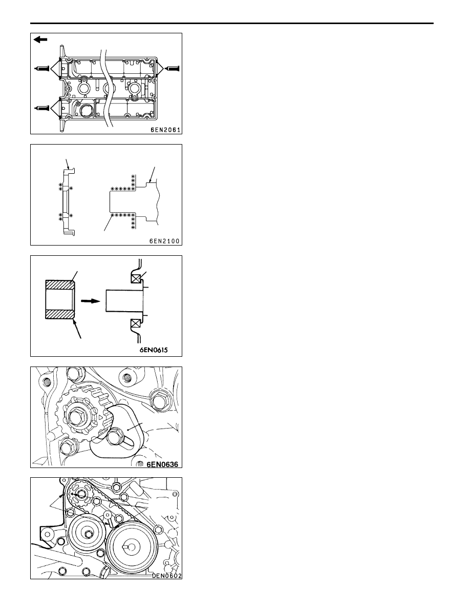
3. Apply form-in-place gasket on the rocker cover at the

position shown in the illustration.
Sealant

Specified sealant:

3M

TM

AAD Part No. 8672 or equivalent

4. Install the rocker cover onto the cylinder head before

the form-in-place gasket hardens.

"

ECRANKSHAFT SPROCKET B INSTALLATION

Clean the crankshaft sprocket B installation surface before

degreasing the crankshaft sprocket B.
NOTE

Always degrease the surface to prevent a drop in the frictional

coefficient at the pressing section caused by the adherence

of oil.

"

FSPACER INSTALLATION

1. Apply a slight amount of oil on the outer periphery of

the spacer (oil seal contact section).

2. Insert the spacer from the chamfered side as shown in

the illustration.
Caution

Reversed insertion of the spacer can cause damage

to the oil seal lip.

"

GACOUNTER BALANCE SHAFT SPROCKET

INSTALLATION

1. Fix the counter balance shaft sprocket with the special

tool.

2. Tighten the counter balance shaft sprocket installation

bolt at the specified torque 46 ± 3 N•m.

"

HTIMING BELT B INSTALLATION

1. Align the crankshaft sprocket B and counter balance shaft

sprocket timing marks with the timing mark on the oil

pump case.

2. Attach the timing belt B to the crankshaft sprocket B

and counter balance shaft sprocket.

Do not loosen the belt tension too much at this time.

Timing belt side

Crankshaft sprocket B

Crankshaft

Degrease

Spacer

Oil seal

Chamfer

MD998785

Timing

marks

Timing

marks

ENGINE OVERHAUL -

Timing Belt

11B-18

3. Confirm that the tensioner B centre and bolt centre are

positioned as shown in the illustration.

4. Apply tension on the timing belt by lifting tensioner B

in the direction of the arrow with a finger, and tension

the tension side until it is “tight”. Fix tensioner B in this

state by tightening the bolt.
NOTE

Make sure that the tensioner B shaft does not rotate

when tightening the bolt. If the shaft rotates, the timing

belt becomes too tense.

5. Connect the special tool (MB991704) to MUT-II and the

battery.

6. Connect the special tool (MB991668) to MUT-II.

7. Rotate the crankshaft clockwise two turns, and align each

timing mark.

8. Select “Belt Tension Measurement” from the MUT-II menu

screen.

9. Separate the special tool (MB991668) 10 to 20 mm from

the centre back between the sprockets (shown with an

arrow), and hold so that it is vertical (inclination within
±15_) in respect to the belt.

10. Lightly tap the section shown with an arrow with fingers,

and measure the belt vibration frequency. If the results

are deviated from the standard value, loosen the bolt,

tension the belt again, and then measure the vibration

frequency again. Repeat this step until the standard value

is attained. Tighten the bolt when the standard value

is attained.
Standard value:

Item

When

check

When

adjusted

When

replaced

Vibration frequency Hz

52 - 92

76 - 92

76 - 92

Deflection

(Reference value) mm

5 - 10

5 - 7

5 - 7

Tensioner

B centre

Installation

bolt centre

Timing

belt B

Belt tension side

Tensioner

B

MB991668

15_

15_

10 - 20 mm

ENGINE OVERHAUL -

Timing Belt

11B-19

Caution

(1) Measure when the belt’s surface temperature is

close to room temperature.

(2) Make sure that water or oil, etc., do not get on

the mike.

(3) If strong winds contact the mike or if noise is

generated in the area while measuring, a value

that differs from the actual value may be indicated.

(4) If the measurement is carried out with the mike

contacted against the belt, a value that differs

from the actual value may be indicated.

(5) Do not measure while the engine is running.

11. Disconnect MUT-II.

12. When measuring with the deflection amount, press the

centre of the tensed side of timing belt B with your index

finger in the arrow direction, and confirm that the deflection

is between 5 and 7 mm.

"

ICRANKSHAFT BOLT/CRANKSHAFT

SPROCKET/CRANKSHAFT SENSING BLADE

INSTALLATION

1. Clean and degrease the crankshaft sprocket, crankshaft

sprocket installation surface of crankshaft and crankshaft

sensing blade, and then install the crankshaft sprocket

and crankshaft sensing blade.

2. Clean the crankshaft bolt hole section.

3. Apply the minimum required amount of engine oil on the

crankshaft bolt section and upper surface of the washer.

4. Fix the flywheel with the special tool.

5. Tighten the crankshaft bolt at the specified torque 162

± 5 N•m.

Timing

marks

Timing

marks

Deflection

amount

Crank-

shaft

bolt

Washer

Crankshaft

sprocket

Crankshaft

sensing blade

Crankshaft

Clean

Degrease

MD998781

ENGINE OVERHAUL -

Timing Belt

11B-20

"

JOIL PUMP SPROCKET INSTALLATION

1. Stop the rotation of the counter balance shaft in the same

manner as for removal.

2. Install the oil pump sprocket.

3. Apply the minimum required amount of engine oil on the

flange nut seat surface.

4. Tighten the flange nut at the specified torque 54 ± 5

N•m.

"

KAUTO TENSIONER INSTALLATION

1. If the auto tensioner rod is in the extended state, set

it with the following steps.

(1) Set the rod of the auto tensioner into a vice so that

it is straight and not inclined.

(2) Press in the rod gradually with the vice, and align

the rod’s set hole A with the cylinder’s set hole B.

(3) Insert a wire (diameter 1.4 mm) into the set holes.

(4) Remove the auto tensioner from the vice.

2. Install the auto tensioner.

Do not remove the wire until the timing belt has been

installed.

"

LTENSIONER PULLEY INSTALLATION

Set the tensioner pulley as shown in the illustration.

"

MATIMING BELT INSTALLATION

1. Set the timing mark on the exhaust side camshaft sprocket

so that it is deviated by one tooth in the counterclockwise

direction from the timing mark on the rocker cover.
NOTE

Even if the sprocket and rocker cover timing marks are

aligned, the exhaust camshaft will return in the

counterclockwise direction by the force of the valve spring

and will stabilize at a position deviated by one tooth.

Phillips driver

A

B

Tensioner pulley holes

Timing marks


Content   ..  158  159  160  161   ..