Mitsubishi Lancer Evolution 7. Manual - part 161


  Index      Mitsubishi     Mitsubishi Lancer Evolution 7 - service repair manual


Search            


Content   ..  159  160  161  162   ..


Mitsubishi Lancer Evolution 7. Manual - part 161


ENGINE OVERHAUL -

Timing Belt

11B-21

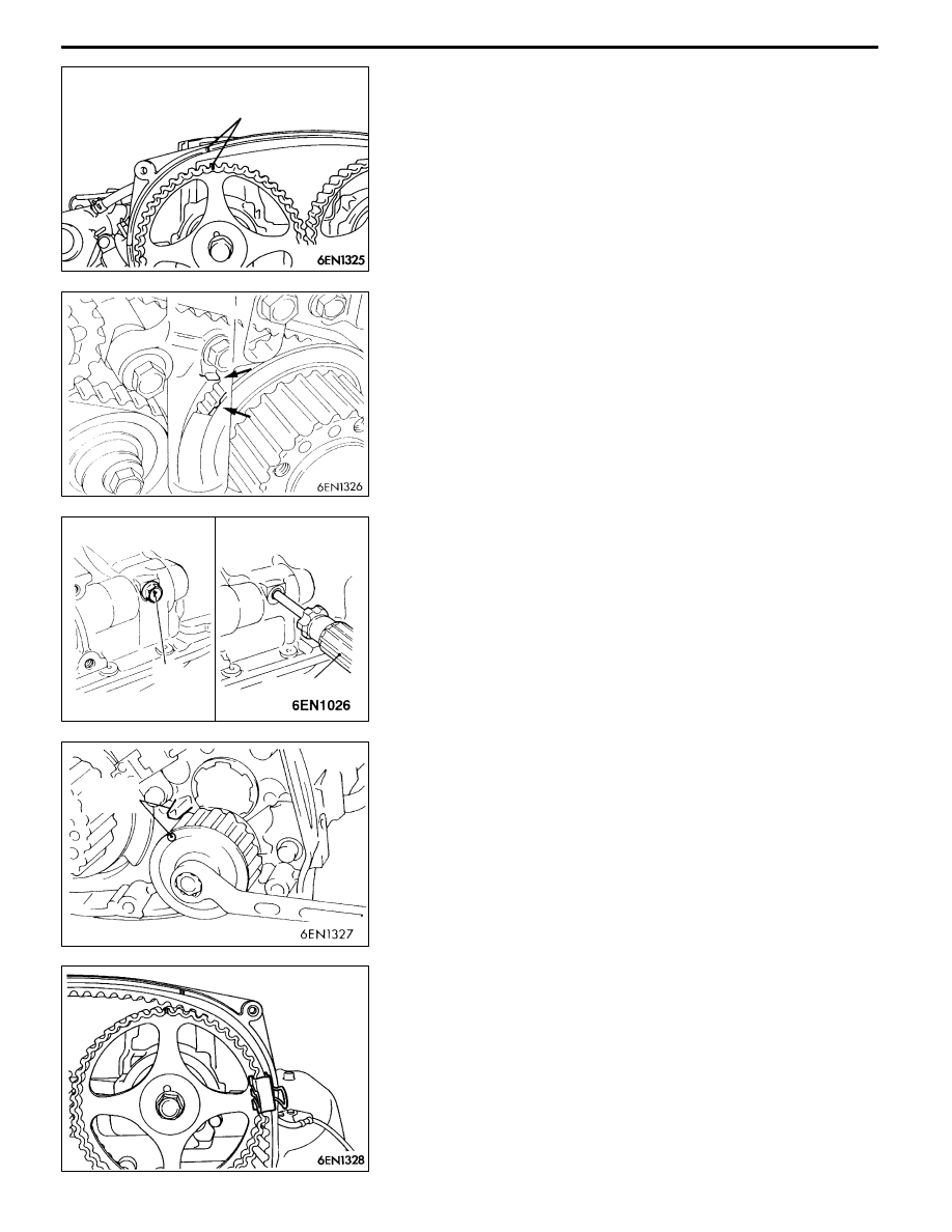
2. Align the timing mark of the intake side camshaft sprocket

to the timing mark on the rocker cover.
NOTE

Even when the sprocket and rocker cover timing marks

are aligned, the intake camshaft will rotate slightly in the

clockwise direction by the force of the valve spring and

will stabilize.

3. Shift and set the crankshaft sprocket timing mark by one

tooth in the counterclockwise direction in the same manner

as the exhaust side camshaft sprocket.

4. Align the oil pump sprocket timing marks.

5. When aligning the oil pump sprocket timing marks, remove

the cylinder block plug, and insert an 8 mm shaft diameter

Phillips driver into the plug hole, and confirm that the

driver shaft can be inserted by 60 mm or more. Do not

remove the Phillips driver until the timing belt has been

attached. If the driver shaft contacts the silent shaft and

only enters 20 to 25 mm, rotate the sprocket once, align

the timing marks again, and then confirm that the Phillips

driver can be inserted by 60 mm or more.

6. Remove the Phillips driver, and set the oil pump sprocket

at a position returned by one tooth in the counterclockwise

direction.

7. Attach the timing belt to the exhaust side camshaft

sprocket, and fix with a paper clip at the position shown

in the illustration.

Timing marks

Phillips driver

Plug

Timing

marks

ENGINE OVERHAUL -

Timing Belt

11B-22

8. Rotate the intake side camshaft sprocket in the

counterclockwise direction. Attach the belt at a position

where the timing mark is deviated by one tooth in the

counterclockwise direction, and then fix with a paper clip.
NOTE

Even if the belt is attached at a position deviated by

one tooth, the intake camshaft will rotate slightly in the

clockwise direction by the force of the valve spring and

will stabilize.

9. Rotate the exhaust side camshaft sprocket in the

clockwise direction, and confirm that the intake side

camshaft sprocket’s timing marks are aligned when the

timing marks are aligned.

10. Attach the timing belt in the order of the idler pulley,

oil pump sprocket and crankshaft sprocket.
NOTE

Attach the timing belt so that it is not deflected.

11. Attach the timing belt to the tensioner pulley.

NOTE

The timing belt can be attached easily to the tensioner

pulley by rotating the intake side camshaft sprocket slightly

in the counterclockwise direction.

12. Rotate the crankshaft sprocket slightly in the clockwise

direction, and remove the timing belt deflection on the

idler pulley side.

13. Confirm that the timing marks on the crankshaft, oil pump

and exhaust camshaft are each deviated by one tooth

in the counterclockwise direction.

Timing marks

Timing marks

Crankshaft

sprocket

Oil pump

sprocket

Crankshaft

sprocket

Crankshaft sprocket

ENGINE OVERHAUL -

Timing Belt

11B-23

14. Using the special tool, rotate the tensioner pulley in the

counterclockwise direction to tense the timing belt, and

then fix by temporarily tightening the tensioner fixing bolt.
NOTE

Remove the deflection of the timing belt between the

intake side and exhaust side camshafts.

15. Rotate the crankshaft in the clockwise direction, and set

the timing mark at the No. 1 cylinder compression top

dead centre.

16. Set the special tool, and screw it in until the wire inserted

when the auto tensioner was installed slightly moves.

17. Loosen the tensioner pulley fixing bolt.

Caution

The timing belt will loosen at this time due to the

rotation of the intake and exhaust camshafts, so make

sure that the timing belt does not deviate.

18. Rotate the special tool and torque wrench in the

counterclockwise direction to remove the timing belt

deflection.

19. From that state, return to the position where the torque

wrench scale reads 3.5 N•m, and then tighten the fixing

bolt.

20. Remove the special tool installed in step 16.

21. Rotate the crankshaft two rotations in the clockwise

direction, and let stand for approx. 15 minutes.

22. Confirm whether the wire inserted when the auto tensioner

was installed can be pulled out easily. If it can be removed

easily, the belt tension is appropriate, so remove the wire.

If the auto tensioner rod’s protrusion amount is at the

standard value, the tension is appropriate.
Standard value: 3.8 - 4.5 mm

23. If the wire cannot be pulled out easily, repeat steps 16

to 21, and tense the belt to the appropriate tension.
Caution

When the crankshaft bolt has been rotated in the

counterclockwise direction, always check the crank-

shaft bolt’s tightening torque. If loosen, re-tighten.

MD998767

MD998738

MD998767

Protru-

sion

amount

ENGINE OVERHAUL -

Timing Belt

11B-24

INSPECTION

1. TIMING BELT

Inspect each section of the belt in detail, and if any of

the following type of damage is found, replace the belt

with a new part.

(1) Hardening of backface rubber.

The backface is glossy, marks are not made even

when a fingernail is run cross it, and there is no

elasticity.

(2) Cracking of backface rubber.

(3) Cracking of canvas.

(4) Cracking at root.

(5) Cracking on side of belt.

(6) Abnormal wear on side of belt.

NOTE

The state is normal if the cutting surface is neat as

if cut with a sharp knife.

(7) Abnormal wear of teeth.

First stages: Canvas is worn (canvas fibres are raised,

rubber is removed and whitish, and canvas seams

are unclear).

Latter stages: Canvas is worn off, and rubber is

exposed (face width is narrow).

(8) Teeth are missing.

2. AUTO TENSIONER

(1) Check for oil leaks. If any leaks are found, replace.

(2) Check whether the rod end is worn or damaged,

and replace if necessary.

(3) Measure the rod protrusion length. If not at the

standard value, replace the auto tensioner.
Standard value: 12 mm

Crack

Crack

Peeling of canvas

Cracking

on side

Cracking at root

Edges are rounded

Abnormal wear

(The core wires are frayed.)

Rubber exposed due to

worn canvas

Teeth are missing

12 mm


Content   ..  159  160  161  162   ..