Mitsubishi Lancer Evolution 7. Manual - part 56
WELDED PANEL REPLACEMENT -
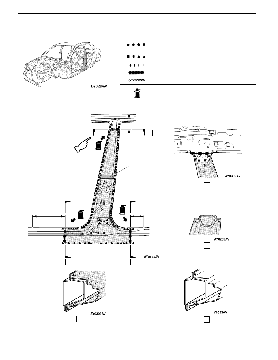
Center Pillar
C-9
CENTER PILLAR
Symbol
Operation description
Spot welding
MIG plug welding (
J
: indicates two panels to be
welded
Y
: indicates three panels to be welded)
MIG spot welding
MIG arc welding (continuous)
Braze welding
Anti-corrosion agent application locations
(Use access holes to apply liberally to butt-welded
joints.)
125±10 mm
290 ± 10 mm
125 ± 10 mm
A
B
C
D
D
B
A
C
Foam acoustic material
REPAIR WELDS
<RS-II>
Caution
Do not use heat at areas using foam material as the foam material may burn.