Mitsubishi Lancer Evolution 7. Manual - part 11


  Index      Mitsubishi     Mitsubishi Lancer Evolution 7 - service repair manual


Search            


Content   ..  9  10  11  12   ..


Mitsubishi Lancer Evolution 7. Manual - part 11


ENGINE -

Emission Control System

1-23

EMISSION CONTROL SYSTEM

The following improvements in the control details have been made to the system, which is basically

the same as the previous system used in the 4G63-DOHC-Turbocharger engine for the EVOLUTION-VI.
D

An electronically-controlled EGR system utilizing an EGR control solenoid valve has been adopted.

D

An electronically-controlled purge control system utilizing purge control solenoid valve has been adopted.

System

Remarks

Evaporative emission control system

Electronic control type

(Duty cycle type purge control solenoid valve)

Exaust gas recirculation (EGR) system

Electronic control type

(Duty cycle type EGR control solenoid valve)

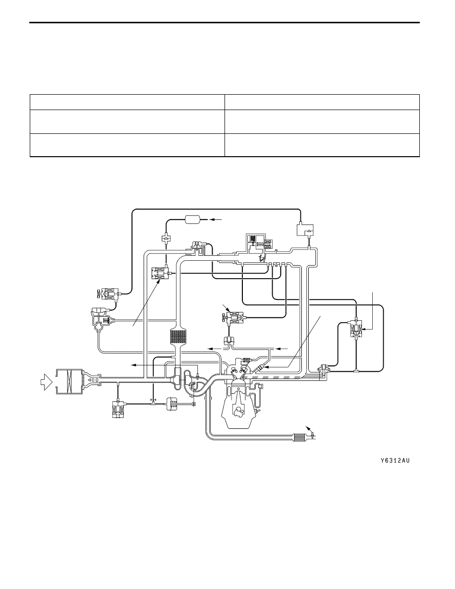
EMISSION CONTROL SYSTEM DIAGRAM

Check

valve

Canister

From

fuel

tank

Purge

control

solenoid

valve

Air

inlet

Oxygen

sensor

(front)

Fuel pressure

control

solenoid valve

Fuel

pressure

regurator

To fuel

tank

PCV valve

From fuel

pump

EGR

valve

Injector

EGR control

solenoid valve

Oxygen sensor (rear)

Three-way

catalytic converter

ENGINE -

Mount

1-24

MOUNT

The inertia axial system based on the past achievements in COLT/LANCER has been adopted for the

engine mount system.
D

Longitudinal installation type of cylindrical liquid-filled engine mount has been adopted for reduction

of idle vibration and improvement of ride feeling.

D

The liquid-filled mount system has been adopted for transmission mount to improve ride feeling by

optimizing the insulator.

D

Installation of roll mount in the upper area has reduced engine rolling. Furthermore, enlargement

of insulator diameter has reduced idle vibration.

CONSTRUCTION DIAGRAM

<Engine mount/Transmission mount>

Transmission mount

Engine mount

ENGINE -

Mount

ENGINE -

Mount

1-25

<Engine roll stopper/Crossmember/Centermember : L.H. drive vehicles>

Rear roll rod bracket

Front roll stopper

Front roll mount bracket

Rear roll mount bracket

Crossmember

Crossmember bar

Centermember

Rear roll rod assembly

<Engine roll stopper/Crossmember/Centermember : R.H. drive vehicles>

Front roll stopper

Front roll mount bracket

Rear roll stopper

Rear roll mount bracket

Crossmember

Crossmember bar

Centermember

ENGINE -

Accelerator System

1-26

ACCELERATOR SYSTEM

The accelerator system is a cable and suspended

pedal combination.

Plastic bushing and rubber damper have been at-

tached to the end of the accelerator cable, to pre-

vent noise and vibration when the cable and accel-

erator arm contact.

CONSTRUCTION DIAGRAM

Accelerator cable

Accelerator

pedal bracket

Accelerator arm

Plastic bushing

Accelerator

cable

Rubber

dumper

Accelerator arm

Accelerator cable

Accelerator

pedal bracket

Accelerator arm

<L.H. drive vehicles>

<R.H. drive vehicles>


Content   ..  9  10  11  12   ..