Mitsubishi Lancer Evolution 7. Manual - part 10


  Index      Mitsubishi     Mitsubishi Lancer Evolution 7 - service repair manual


Search            


Content   ..  8  9  10  11   ..


Mitsubishi Lancer Evolution 7. Manual - part 10


ENGINE -

Control System

1-19

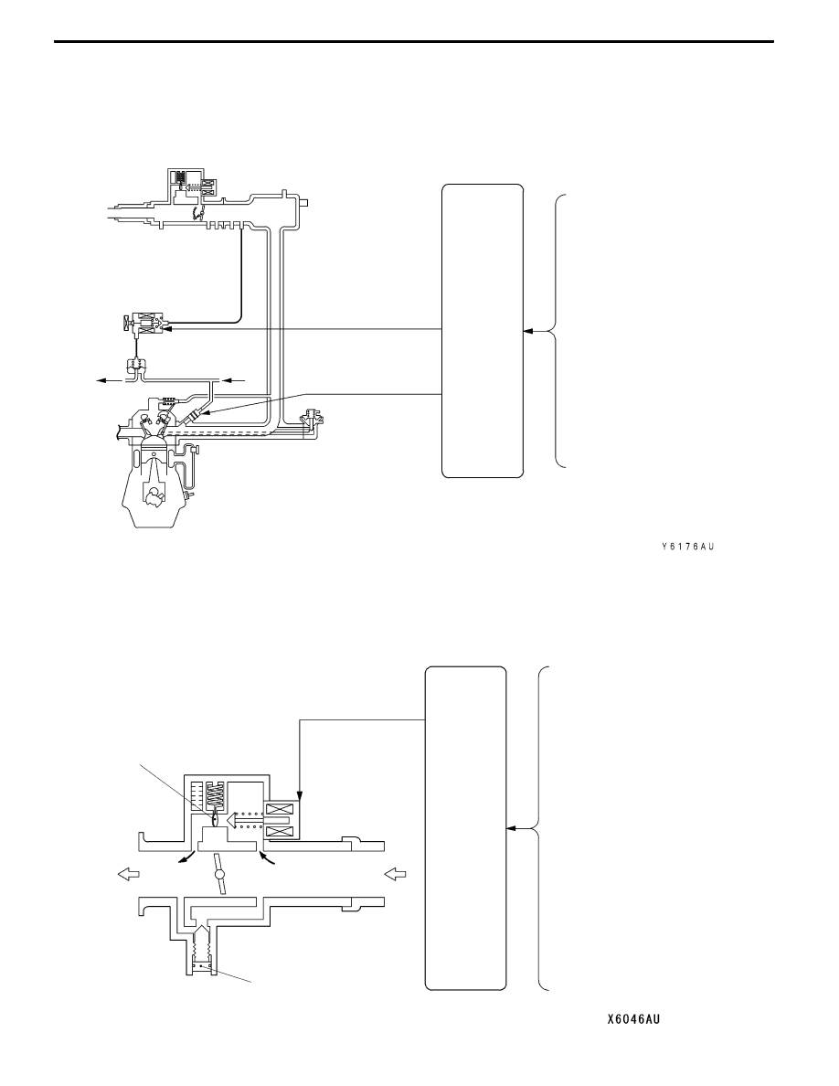
FUEL INJECTION CONTROL

The fuel injection control system is basically the same as the control system for the 4G63-DOHC-Turbocharger

engine installed in the Evolution-VI.
SYSTEM CONFIGURATION DIAGRAM

Air flow sensor

Intake air temperature sensor

Engine coolant temperature sensor

Throttle position sensor

Crank angle sensor

Camshaft position sensor

Vehicle speed sensor

Ignition switch-ST

Oxygen sensor

Barometric pressure sensor

Engine-ECU

To fuel

tank

Fuelpressure

regulator

From

fuel

pump

Injector

Fuel pressure control

solenoid valve

Detonation sensor

IDLE SPEED CONTROL

The idle speed control system is basically the same as the control system for the 4G63-DOHC-Turbocharger

engine installed in the Evolution-VI.
SYSTEM CONFIGURATION DIAGRAM

Air flow sensor

Intake air temperature sensor

Engine coolant temperature sensor

Throttle position sensor

Crank angle sensor

A/C switch

Vehicle speed sensor

Ignition switch-ST

Diagnosis control terminal

Speed adjusting screw

Bimetal type limiter

From air

cleaner

To intake

manifold

A/C load signal

Power steering fluid pressure switch
Alternator FR terminal
Ignition switch-IG

Engine-ECU

Idle speed con-

trol servo

(Stepper motor)

Barometric pressure sensor

ENGINE -

Control System

1-20

IGNITION TIMING AND DISTRIBUTION CONTROL

The ignition timing and distribution control system is basically the same as the control system for the

4G63-DOHC-Turbocharger engine installed in the Evolution-VI.
SYSTEM CONFIGURATION DIAGRAM

Intake air temperature sensor

Engine coolant temperature sensor

Crank angle sensor

Camshaft position sensor

Vehicle speed sensor

Ignition switch-ST

Ignition

coil A

Ignition switch

Battery

Spark plug

Ignition

coil B

To tachometer

Cylinder No. 4

1

3

2

Barometric pressure sensor

Engine-

ECU

Detonation sensor

Air flow sensor

RADIATOR FAN MOTOR CONTROL

The radiator fan motor control system is basically the same as the control system for 4G6-MPI engine

installed in the GALANT.

POWER SUPPLY AND A/C CONDENSER FAN RELAY CONTROL, OXYGEN

SENSOR HEATER CONTROL, AIR FLOW SENSOR FILTER RESET CONTROL,

ALTERNATOR CONTROL, FUEL PRESSURE CONTROL, SUPERCHARGING

PRESSURE CONTROL, SECONDARY AIR CONTROL

These control systems are basically the same as those for 4G63-DOHC-Turbocharger engine installed

in the EVOLUTION-VI.

ENGINE -

Control System

1-21

FUEL PUMP RELAY CONTROL

D

The fuel injection amount is controlled by the fuel pump relay 3 in order to reduce the amount of

return fuel when the engine is running at low speeds and fuel consumption is low, and also to reduce

noise.

Fuel pump relay 1

Fuel pump relay 2

Fuel

pump

relay 3

Battery

Ignition switch

Fuel pump resistor

To fuel pump

Engine-ECU

ENGINE -

Control System

1-22

EGR CONTROL AND PURGE CONTROL

Refer to the EMISSION CONTROL SYSTEM.

DIAGNOSIS SYSTEM

The engine-ECU is prvided with the following functions to make system inspection easier.
D

Engine warning lamp control

D

Diagnosis function

D

Service data output

D

Actuator test

NOTE

Refer to the Workshop Manual for details on each item.


Content   ..  8  9  10  11   ..