Mitsubishi Lancer Evolution 7. Manual - part 9
ENGINE -
Control System
1-15
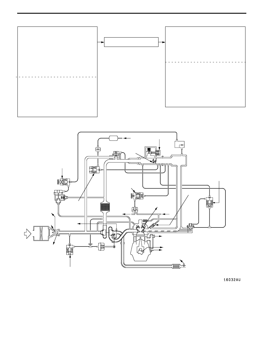
CONTROL SYSTEM DIAGRAM
L
1 Oxygen sensor (front)
L
2 Oxygen sensor (rear)
L
3 Air flow sensor
L
4 Intake air temperature sensor
L
5 Throttle position sensor
L
6 Camshaft position sensor
L
7 Crank angle sensor
L
8 Barometric pressure sensor
L
9 Engine coolant temperature sensor
L
10 Detonation sensor
l
1 Injector
l
2 Idle speed control servo
l
3 Fuel pressure control solenoid valve
l
4 Waste gate solenoid valve
l
5 EGR control solenoid valve
l
6 Purge control solenoid valve
l
7 Secondary air control solenoid valve
D
Power supply
D
Ignition switch-IG
D
Ignition switch-ST
D
Vehicle speed sensor
D
A/C switch
D
A/C l
oad signal
D
Power steering fluid pressure switch
D
Alternator FR terminal
D
Engine control relay
D
Fuel pump relay 2, 3
D
A/C relay
D
Ignition coil
D
Fan controller
D
Condenser fan relay (HI)
D
Condenser fan relay (LOW)
D
Engine warning lamp
D
Diagnosis output
D
Alternator G terminal
Engine-ECU
L
1 Oxygen
sensor
(front)
L
4 Intake air
temperature
sensor
L
5 Throttle
position
sensor
L
6 Camshaft
position sensor
l
1 Injector
l
2 Idle
speed
control
servo
l
6 Purge
control
solenoid
valve
Three-way
catalytic converter
Canister
Air
inlet
Vacuum
tank
Fuel
pressure
regurator
From
fuel tank
To fuel tank
PCV valve
From
fuel pump
Waste gate
actuator
L
2 Oxygen sensor (rear)
Check
valve
By-pass
valve
l
5 EGR control
solenoid valve
l
4 Waste gate
solenoid valve
L
8 Barometric
pressure
sensor
L
3 Air flow
sensor
l
7 Secondary
air control
solenoid
valve
Secondary
air valve
l
3 Fuel pressure
control
solenoid valve
EGR
valve
L
9 Engine coolant
temperature sensor
L
7 Crank angle sensor
L
10 Detonation sensor