Mitsubishi Lancer Evolution 7. Manual - part 7


  Index      Mitsubishi     Mitsubishi Lancer Evolution 7 - service repair manual


Search            


Content   ..  5  6  7  8   ..


Mitsubishi Lancer Evolution 7. Manual - part 7


ENGINE -

Intake and Exhaust

1-7

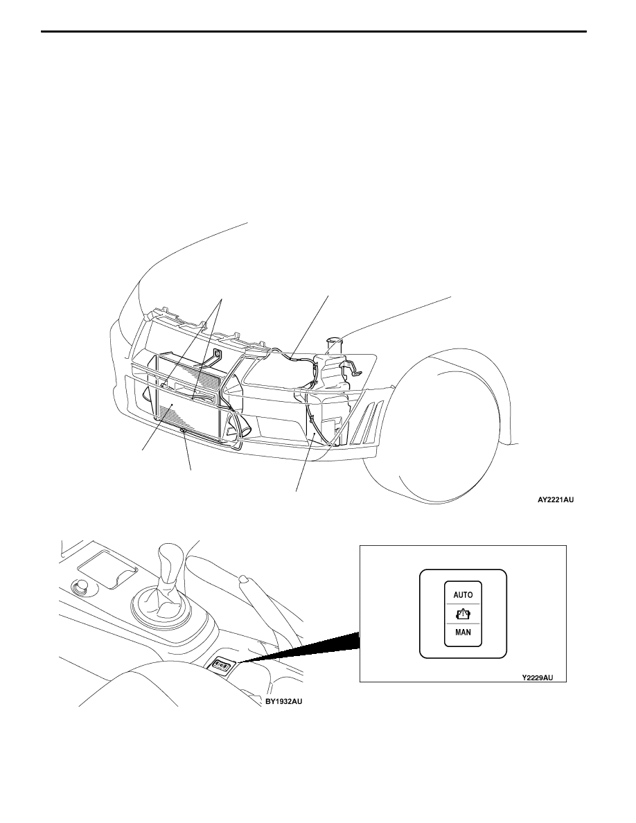
INTER COOLER WATER SPRAY
To complement the intercooler efficiency in ranges where the cooling efficiency of the air cooled intercooler

is insufficient, and attain high performance in various operating environments, a system which cools by

spraying water from a special washer tank for the intercooler to the front of the intercooler has been

adopted.

The features of the intercooler water spray system is as follows.
D

Sprays water when the water spray switch on the floor console is operated.

D

Adopts a system which enables switching between the auto mode which automatically sprays water

at the optimum operating conditions by signals from the ECU according to the engine state, and

the manual mode which is operated by the driver.

D

Three water spray nozzles are located at optimum positions to enhance the intercooler efficiency.

CONSTRUCTION DIAGRAM

<Water Spray Nozzle/Water Spray Hose/Washer Tank>

Inter cooler

Water spray hose

Water spray nozzle

Water spray nozzle

Washer tank

<Water Spray Switch>

Water spray switch

ENGINE -

Intake and Exhaust

1-8

SYSTEM DIAGRAM

M

Ignition switch (IG2)

Ignition switch (IG1)

J/B

OFF

ON

Water spray relay

Water spray

motor

Engine-ECU

J/B

7.5A

7.5A

MANUAL

AUTO

Water spray switch

J/C

J/C

Combination

meter

Fuse

20A

Fuse

7.5A

Front-ECU

(Tail lamp relay)

ENGINE -

Exhaust System

1-9

EXHAUST SYSTEM

EXHAUST FITTING BRACKET
An exhaust fitting bracket has been added in order to provide

greater rigidity.

TURBOCHARGER
The turbocharger type TD05HR-16G6-9.8T and TD05HRA-16G6-9.8T have been adopted.

Compared to previous types of turbocharger, these new types have a smaller turbine housing nozzle

area which improves response at medium to low speeds.

Section A - A

Nozzle area

A

A

Exhaust fitting

Exhaust fitting bracket

Exhaust manifold

heat protector

ENGINE -

Intake and Exhaust

1-10

EXHAUST PIPE AND MUFFLER
Exhaust pipe consisting of 3 separation system: front exhaust pipe, center exhaust pipe, and exhaust

main muffler, has the following features:
D

The adoption of a seal ring has reduced vibrations during idling and driving noise.

D

A main muffler incorporating a back pressure variable valve is adopted.

D

Straight layout of exhaust piping has reduced vibration and exhaust pressure in exhaust system.

D

The adoption of hanger rubber with lower spring constant and the decreased number of hangers

have reduced vibration in exhaust piping.

D

The adoption of all stainless exhaust piping has enhanced resistance to corrosion and heat.

D

Installation of thermal insulating cover and materials on front pipe has improved emission control

performance.

CONSTRUCTION DIAGRAM

Center exhaust pipe

Main muffler

Pre-muffler

Catalytic converter

Front exhaust pipe

Seal ring

Pre-muffler (sub)

Oxygen sensor

When valve

is open

Back

pressure

variable

valve

Flow of exhaust gas


Content   ..  5  6  7  8   ..