Mitsubishi Lancer Evolution VI. Manual - part 116


  Index      Mitsubishi     Mitsubishi Lancer Evolution VI - service repair manual


Search            


Content   ..  114  115  116  117   ..


Mitsubishi Lancer Evolution VI. Manual - part 116


  – Heater Control Assembly and A/C Switch

HEATER AND MANUAL
AIR CONDITIONER

55-16

INSTALLATION SERVICE POINT

"

A

A

HEATER CONTROL ASSEMBLY INSTALLATION

1.

Cut off the bosses and clamp shown before installing
a new heater control assembly.

2.

Install the heater control assembly mounting screws.

3.

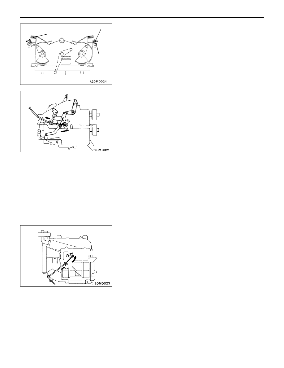
Follow the steps below to install the air outlet changeover
damper lever cable.
(1) Set the air outlet changeover link of the heater unit

to the DEF position.

(2) Set the air outlet changeover control knob on the

heater control assembly to the DEF position.

(3) After inserting the inner cable into the link, pull the

outer cable to the heater control assembly side and
then fasten the outer cable to the clip of the heater
unit.

(4) After installation, operate the heater control knob to

check if the mode changeover can be accomplished
smoothly.

4.

Follow the steps below to install the air mix damper lever
cable.
(1) Set the air mix damper link on the heater unit to

the MAX HOT position.

(2) Set the air mix damper knob of the heater control

assembly to the MAX HOT position.

(3) After inserting the inner cable into the link, pull the

outer cable to the heater control assembly side and
then fasten the outer cable to the clip of the heater
unit.

(4) After installation, operate the heater control knob to

check if the air mix damper can be actuated smoothly.

Clamp

Boss

Boss

DEF
position

MAX HOT position

  – Heater Control Assembly and A/C Switch

HEATER AND MANUAL
AIR CONDITIONER

55-17

5.

Follow the steps below to install the inside/outside air
changeover damper lever cable.
(1) Set the inside/outside air changeover damper link

on the blower unit to the INSIDE position.

(2) Set the inside/outside air changeover damper knob

of the heater control assembly to the INSIDE position.

(3) After inserting the inner cable into the link, pull the

outer cable to the heater control assembly side and
then fasten the outer cable to the clip of the blower
unit.

(4) After installation, ensure that inside/outside air

changeover damper operates smoothly by operating
the heater control assembly knob.

INSPECTION

A/C SWITCH CONTINUITY CHECK

Switch

iti

Terminal No.

position

1

ILL

2

IND

4

5

7

OFF

ON

BLOWER SWITCH CONTINUITY CHECK

Switch position

Terminal No.

1

2

3

5

6

7

8

OFF

D

 (LO)

D

 (ML)

D

  (MH)

D

 (HI)

INSIDE position

Push

OFF

ON

  – Heater Unit and Blower Unit

HEATER AND MANUAL
AIR CONDITIONER

55-18

HEATER UNIT AND BLOWER UNIT 
<VEHICLES WITHOUT AIR CONDITIONER>

REMOVAL AND INSTALLATION

Pre-removal and Post-installation Operation

D

Engine Coolant Draining and Refilling

D

Air Cleaner Cover and Hose Removal and
Installation

D

Floor Console and Instrument Panel Removal and
Installation

D

Rear Seat Heater Duct Removal and Installation
<Vehicles for cold regions> (Refer to P.55-31.)

1

3

4

5

6

2

7

8

9

10

11

Removal steps

1. Center reinforcement RH
2. Heater control assembly
3. Center reinforcement LH
4. Center ventilation duct
5. Foot distribution duct
6. Joint duct

7. Blower unit
8. Heater hose
9. Heater unit

10. Heater core support

11. Heater core

  – Heater Unit, Cooling and Blower Unit

HEATER AND MANUAL
AIR CONDITIONER

55-19

HEATER UNIT, COOLING AND BLOWER UNIT 
<VEHICLES WITH AIR CONDITIONER>

REMOVAL AND INSTALLATION

Pre-removal and Post-installation Operation

D

Engine Coolant Draining and Refilling

D

Discharging and Charging of Refrigerant 
(Refer to P.55-6.)

D

Air Cleaner Cover and Hose Removal and
Installation

D

Floor Console and Instrument Panel Removal and
Installation

D

Rear Seat Heater Duct Removal and Installation
<Vehicles for cold regions> (Refer to P.55-31.)

1

3

4

5

6

2

7

8

9

10

11

12

Piping connection

O-ring

A/C Compressor oil: SUN PAG 56

Removal steps

1. Center reinforcement RH
2. Heater control assembly
3. Center reinforcement LH
4. Center ventilation duct
5. Foot distribution duct
6. Drain hose

A

A

"

7. Connection between cooling unit

and refrigerant line

8. Cooling and blower unit
9. Heater hose

10. Heater unit

11. Heater core support

12. Heater core

REMOVAL SERVICE POINT

A

A

"

REMOVAL OF REFRIGERANT LINE FROM
COOLING UNIT

Plug the open end of the removed hose and the opening
in the cooling unit to prevent entry of dust and foreign
substances.

Caution
Compressor oil and the receiver are highly
moisture-absorptive. 
Do not use plugs allowing ventilation.


Content   ..  114  115  116  117   ..