Mitsubishi Lancer Evolution VI. Manual - part 115


  Index      Mitsubishi     Mitsubishi Lancer Evolution VI - service repair manual


Search            


Content   ..  113  114  115  116   ..


Mitsubishi Lancer Evolution VI. Manual - part 115


HEATER AND MANUAL AIR CONDITIONER – 

On-vehicle Service

55-12

Caution
(1) To connect the quick joint, press section “A” firmly

against the service valve until a click is heard.

(2) When connecting, run your hand along the hose

while pressing to ensure that there are no bends
in the hose.

5.

Start the engine.

6.

Set the blower switch to HI (Fast) position

7.

Set the A/C switch to ON position

8.

Set the temperature control to Max. cooling position

9.

Set the mode selection to Face position

10. Set the air selection to Recirculation position
11. Fix engine speed to 1,500 r/min.
12. Check that the high-pressure side pressure is 1,667 –

1,765 kPa.

NOTE
If the pressure is not within this range, adjust it as follows;
cool down the condenser using a cooling fan if the
pressure is higher, and cover the condenser to protect
it from ventilation air if it is lower.

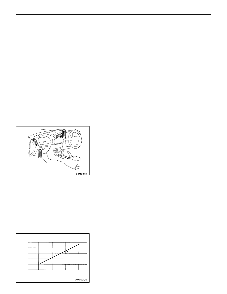
13. Set a dry-bulb/wet-bulb thermometer at the air inlet, and

set a dry-bulb thermometer at the air outlet.

Caution
(1) Set the dry-bulb thermometer at a position where

the temperature sensing section can be directly
blown with cooled air.

(2) Place the dry-bulb/wet-bulb thermometer at a

position where it is not exposed to cooled air
blown out.

14. After the temperature of the air blown out from the air

outlet has been stabilized (10 – 15 minutes after starting),
read the dry-bulb thermometer set at the air outlet and
the wet-valve thermometer set at the air inlet.

15. The air conditioning system is considered in good

condition if the intersecting point of the measurements
obtained in Step (14) is below the performance evaluation
reference line on the graph.

Caution
Do not remove the quick joint immediately after the
performance test has been completed. Stop the engine
and wait until the high-pressure side pressure of the
gauge manifold has been lowered sufficiently.

Dry-bulb ther-
mometer

Dry-bulb/wet-bulb
thermometer

Reading of wet-bulb thermometer
set at air inlet (

°

C)

Performance
evaluation
reference line

In order

Not in order

0

Reading of dry-bulb

thermometer set at air outlet

(

°

C)

15

20

25

30

5

10

15

20

25

HEATER AND MANUAL AIR CONDITIONER – 

On-vehicle Service

55-13

DUAL PRESSURE SWITCH SIMPLE CHECK

Measure the high-pressure side pressure. If there is a
continuity between the dual pressure switch terminals with
the dual pressure switch in ON condition as shown in the
graph at left, the switch is in good condition. If not, it is faulty.
Replace the switch.

POWER RELAY CHECK

BLOWER RELAY

Battery voltage

Terminal No.

1

3

2

5

Power is not supplied

Power is supplied

Dual pressure switch

ON

Pressure

196 

±

 20

221

2,354 

±

 196 2,942 

±

 196

OFF

kPa

Blower relay

HEATER AND MANUAL AIR CONDITIONER – 

On-vehicle Service

55-14

A/C COMPRESSOR RELAY, CONDENSER FAN RELAY

Battery voltage

Terminal No.

1

3

4

5

Power is not supplied

Power is supplied

IDLE-UP OPERATION CHECK

1.

Before inspection and adjustment, set vehicle in the
pre-inspection condition:

2.

Check whether or not the idle speed is the standard value.

Standard value: 700 

±

 50 r/min

NOTE
There is no necessity to make an adjustment, because
the idle speed is automatically adjusted by the ISC system.
If, however, there occurs a deviation from the standard
value for some reason, check the fuel control system.

3.

When the A/C is running after turning the A/C switch
to ON, check to be sure that the idle speed is at the
standard value.

Standard value: 850 

±

 50 r/min

Fan control relay

Compressor
relay

Radiator
fan relay

Condenser
fan relay

 – Heater Control Assembly and A/C Switch

HEATER AND MANUAL
AIR CONDITIONER

55-15

HEATER CONTROL ASSEMBLY AND A/C SWITCH

REMOVAL AND INSTALLATION

Pre-removal and Post-installation Operation

D

Instrument Lower Panel and Heater Control Panel
Removal and Installation

D

Floor Console Assembly Removal and Installation

D

Foot Duct Removal and Installation 
(Refer to P.55-31.)

3

4

1

2

5

Removal steps

A

A

" "

A

A

1. Heater control assembly
2. Rear window defogger switch
3. A/C switch
4. Knob
5. Blower switch

REMOVAL SERVICE POINT

A

A

"

HEATER CONTROL ASSEMBLY REMOVAL

1.

Remove the heater control assembly mounting screws.

2.

Bend the clamp and the bosses (2 each side), which
are inserted into the centre reinforcement.

3.

Remove the heater control assembly.

Clamp

Boss

Boss


Content   ..  113  114  115  116   ..