Mitsubishi Lancer Evolution VI. Manual - part 113
HEATER AND MANUAL AIR CONDITIONER –
Troubleshooting
55-4
TROUBLESHOOTING
TROUBLESHOOTING PROCEDURES
1.
Check air ducts, control rods, etc. for improper connection.
2.
Check that the electrical connectors of the relevant components are connected securely and the
fuse is not blown.
3.
Perform the troubleshooting as follows; first understand the items to be inspected and the the procedures
comprehensively using Trouble Symptom/Failed Component Cross-Reference Table and then inspect
the appropriate items sequentially.
4.
Be sure to perform each component check after disconnecting the relevant connector.
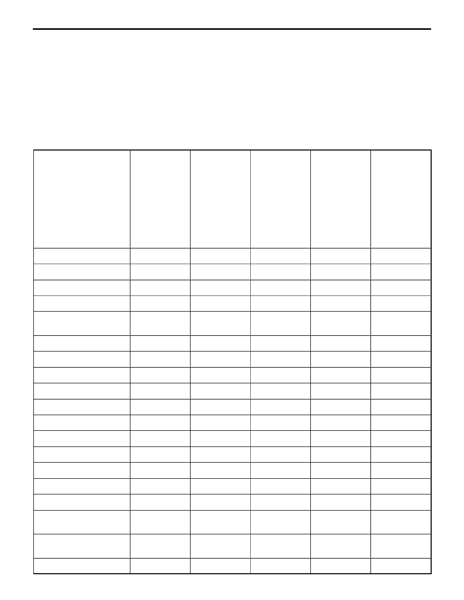
Trouble Symptom/Failed Component Cross-Reference Table
Items to be checked
1.
When the igni-
tion switch is
“ON”, the A/C
does not oper-
ate.
2.
When the A/C
is operating,
temperature
inside the pas-
senger
compartment
does not
decrease (cool
air is not
emitted).
3.
Blower fan
motor does not
turn.
4.
Blower fan
motor does not
stop turning.
5.
When A/C is
operating,
radiator fan
and condenser
fan do not run.
Fuse
1
1
1
Harness, connector
2
2
1
2
Amount of refrigerant
3
1
A/C compressor relay
4
A/C compressor magnet
clutch
5
Dual pressure switch
6
2
3
A/C switch
7
Blower switch
8
3
2
Blower relay
4
Resistor
5
3
Blower motor
6
Air thermo-sensor
9
3
Condenser fan relay
4
4
Condenser fan motor
5
5
Radiator fan relay (HI, LO)
6
6
Radiator fan motor
7
7
Refrigerant temperature
switch
10
8
Auto compressor control
unit
11
9
Engine-ECU
12
10
8