Mitsubishi Lancer Evolution VI. Manual - part 111
CHASSIS ELECTRICAL –
Speaker / Antenna
54-48
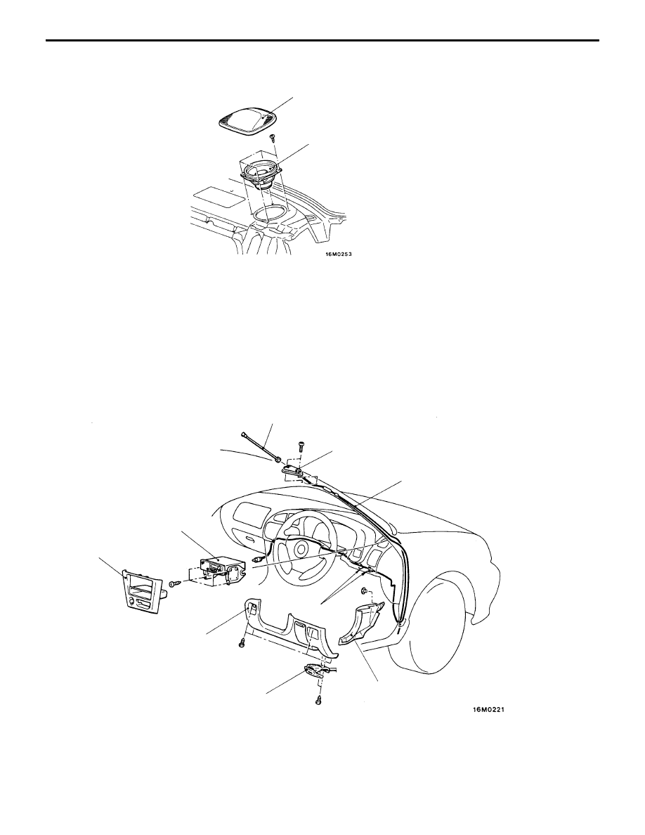
<REAR SPEAKER>
7
6
Rear shelf speaker removal steps
6. Speaker garnish
7. Speaker
ANTENNA
POLE ANTENNA
REMOVAL AND INSTALLATION
1
2
3
5
4
7
6
8
9
Removal steps
1. Pole
2. Radio panel
3. Radio and tape player
4. Hood lock release handle
5. Driver side lower cover
6. Clip
7. Cowl side trim
A
A
"
8. Antenna assembly
9. Antenna base gasket