Mitsubishi Lancer Evolution VI. Manual - part 109
CHASSIS ELECTRICAL –
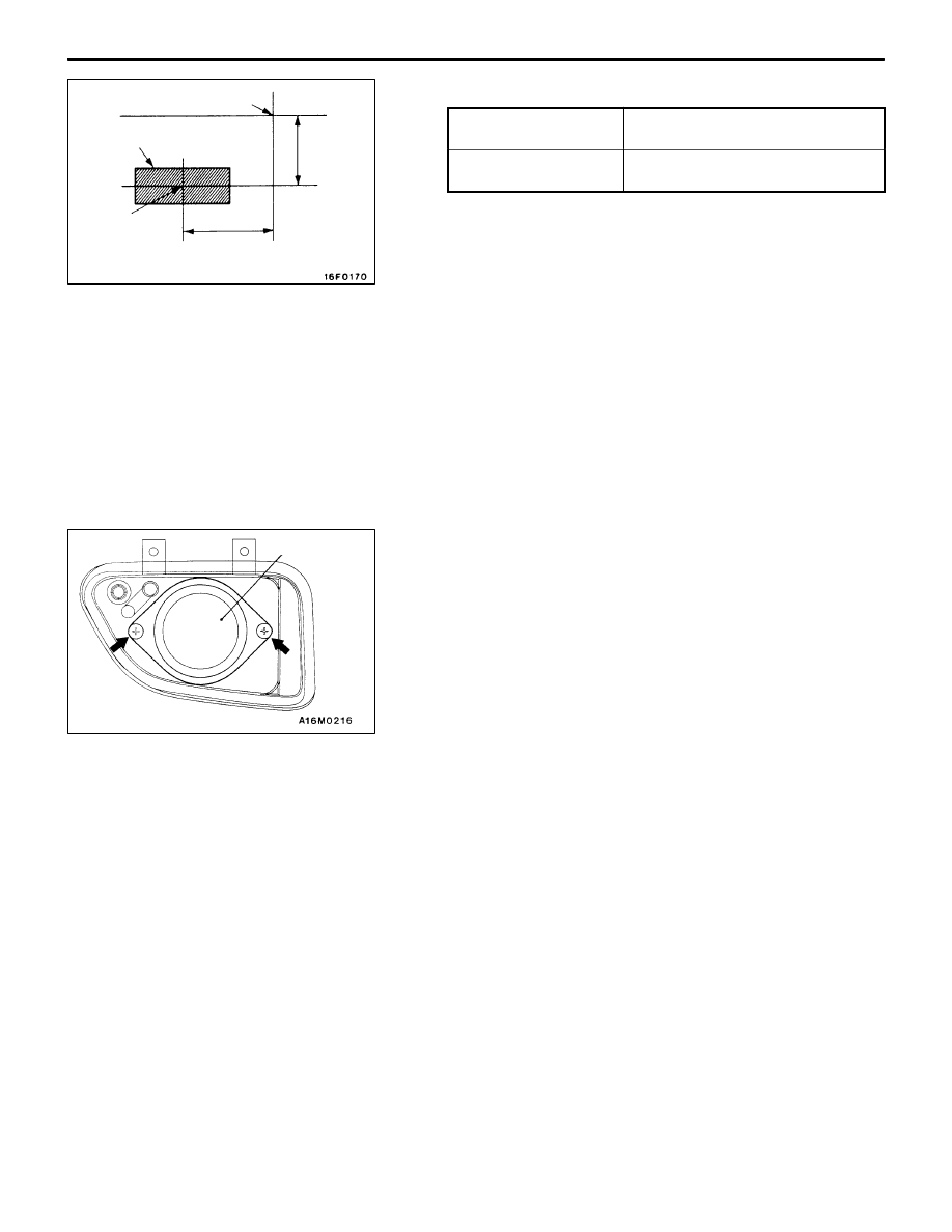
Front Fog Lamp
54-40
Standard values:
Vertical direction
2
°
(349 mm) below horizontal line
(H)
Horizontal direction
3
°
(524 mm) leftward from
vertical line (V)
Caution:
(1) Perform aiming adjustments, one light at a time,
with the other headlamp disconnected so as not
to be lit unless circumstances compel otherwise.
When reconnecting the headlamps, be careful not
to upset their aim. Do not leave the headlamps
on for any longer than 3 minutes if their outer
lenses are covered with a surface covering
impervious to light.
(2) Do not mask the outer lenses by taping or in any
other way.
(3) Aiming adjustment must be completed with the
aiming adjustment screws turned in the tightening
direction.
FOG LAMP BULB REPLACEMENT
1.
Remove the fog lamp.
2.
Remove the cover.
3.
Unhook the spring which secures the bulb and then
replace the bulb.
Caution
(1) Do not touch the surface of the bulb with hands
or dirty gloves. If the surface does become dirty,
clean it with alcohol or thinner, and let it dry
thoroughly before installing.
(2) To prevent the clouding of lens and ingress of
water into the lamp unit, install the socket cover
correctly.
Lamp center
Vertical
direction
High
intensity
zone
center
(optical
axis)
High intensity zone
Horizontal direction
V
H
Cover