Mitsubishi Lancer Evolution VI. Manual - part 110
CHASSIS ELECTRICAL –
Hazard Warning Lamp Switch, Clock
ILL
ILL
54-44
HAZARD WARNING LAMP SWITCH, CLOCK
SPECIAL TOOL
Tool
Number
Name
Use
MB990784
Ornament remover
Air conditioner panel removal
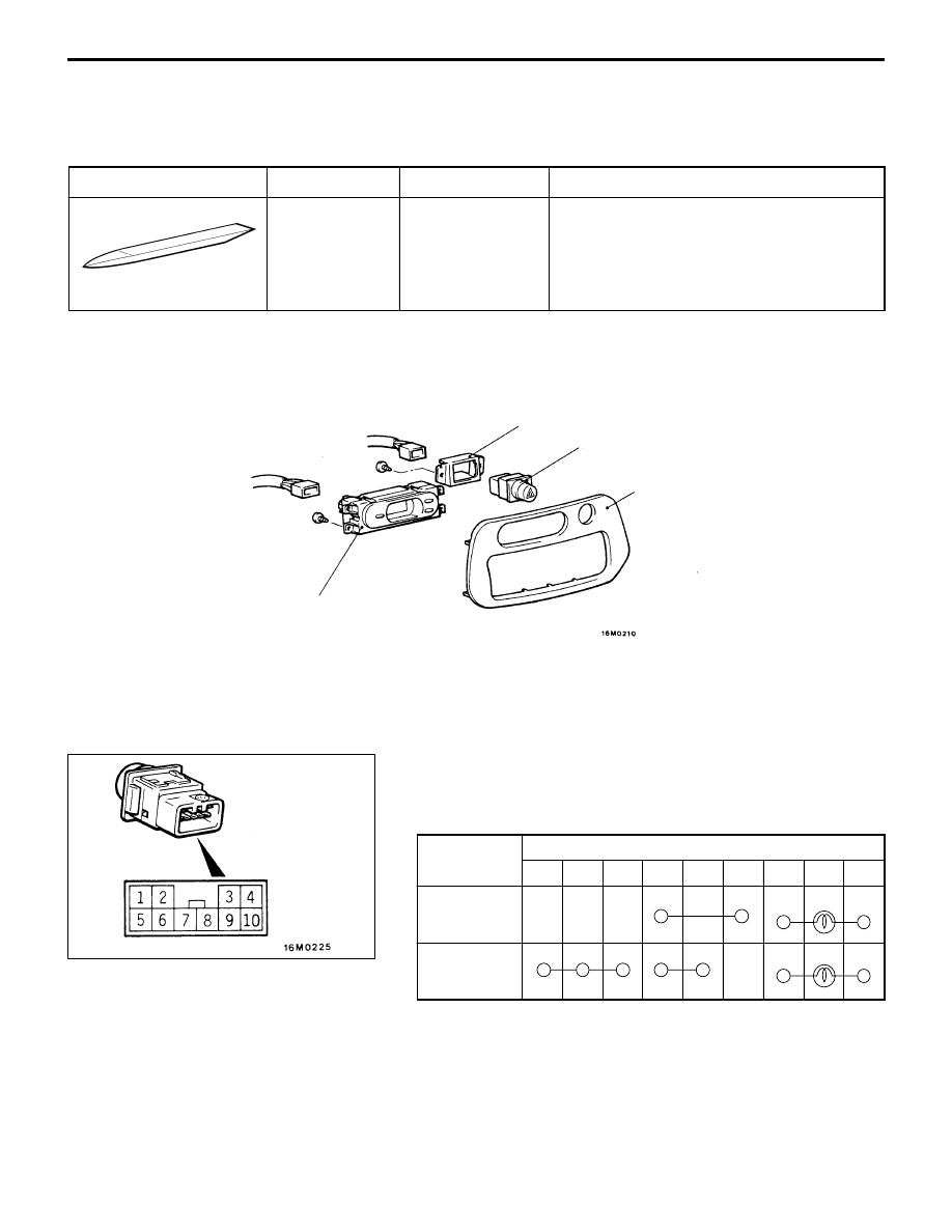
HAZARD WARNING LAMP SWITCH
REMOVAL AND INSTALLATION
2
1
3
4
Hazard warning lamp switch
removal steps
1. Air conditioner panel
2. Switch holder
3. Hazard warning lamp switch
Clock removal steps
1. Air conditioner panel
4. Clock
INSPECTION
HAZARD WARNING LAMP SWITCH CONTINUITY
CHECK
Switch
iti
Terminal No.
position
1
2
4
5
6
7
9
–
10
OFF
ON