Mitsubishi Lancer Evolution VI. Manual - part 107


  Index      Mitsubishi     Mitsubishi Lancer Evolution VI - service repair manual


Search            


Content   ..  105  106  107  108   ..


Mitsubishi Lancer Evolution VI. Manual - part 107


CHASSIS ELECTRICAL – 

Headlamp

54-32

HEADLAMP

SERVICE SPECIFICATIONS

Items

Standard value

Limit

Headlamp
aiming

High
beam

Vertical direction

25’ (22 mm) below horizontal line

aiming
[Parenthe-
sized are
allowable

beam

Horizontal
direction

Left head-
lamp

Parallel to direction of vehicle travel

allowable
beam axis
deviations 3
m ahead of

Right head-
lamp

15’ (13 mm) leftward from vertical line (V)

m ahead of
headlamp.]

Low
beam

Vertical direction

25’ (22 mm) below horizontal line

p ]

beam

Horizontal direction

Position where 15* rising section intersects
vertical line (V)

Headlamp intensity cd (Center of high-beam high intensity
zone)

15,000 or
more per
light

Cautions in Handling Headlamp Assembly

Each headlamp assembly has a plastic outer lens on. Observe the do’s and don’ts below when
handling the headlamps.

D

Do not leave the headlamps lit for longer than 3 minutes with a protective cover on.

D

Do not mask the outer lens surface by taping or in any other way.

D

Do not scrub the outer lens surface with a pointed tool.

D

Use the designated wax remover for cleaning the outer lens surface. Rinse it thoroughly.

D

Use the designated genuine bulbs.
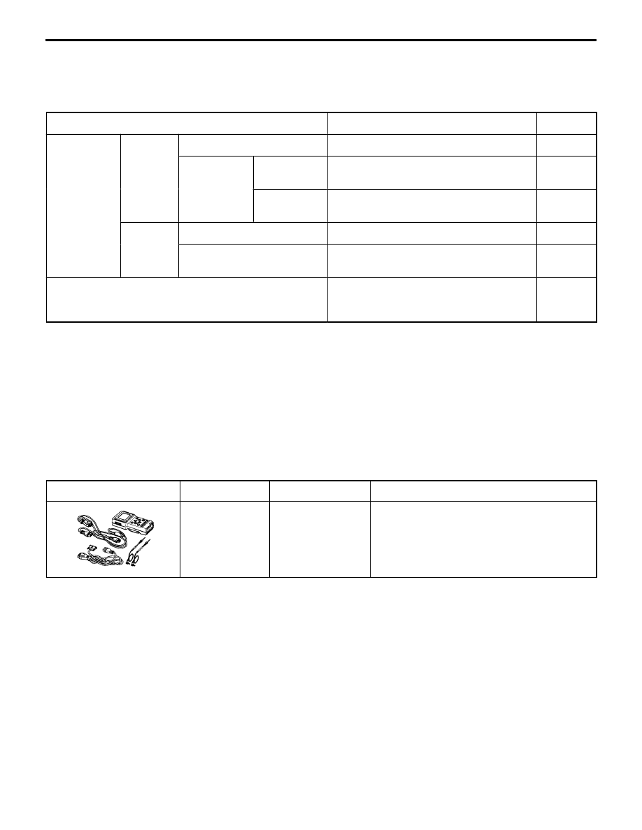
SPECIAL TOOLS

Tool

Number

Name

Use

MB991502

MUT-

II

 sub as-

sembly

ETACS-ECU input signal checking

CHASSIS ELECTRICAL – 

Headlamp

54-33

TROUBLESHOOTING

DIAGNOSIS FUNCTION

INPUT SIGNAL INSPECTION POINTS <VEHICLES WITH ETACS-ECU>

Refer to Group 00 – How to Use Troubleshooting / Inspection Service Points.

The lighting monitor buzzer does not sound even when
the ignition key is removed with the tail lamps or
headlamps ON and the driver’s side door open. [However,
the key reminder warning buzzer sounds when inserting
the key into the ignition key cylinder.

Probable cause

The cause is probably a malfunction of the lighting switch input circuit system or
a malfunction of ETACS-ECU or buzzer ECU. When the key reminder warning buzzer
is sounding, the lighting monitor warning buzzer does not sound even if the tail lamps
or headlamps are lit.

D

Malfunction of harness or connector

D

Malfunction of ETACS-ECU

D

Malfunction of buzzer ECU

<Vehicles with ETACS-ECU>
MUT-

II

 Pulse check

OK: MUT-

II

 buzzer sounds once

when the lighting switch is
turned from OFF to TAIL or
HEAD.

NG

Check the following connectors.
B-79

Repair

OK

Check trouble symptom.

NG

OK

Replace the ETACS-ECU.

<Vehicles with buzzer ECU>

NG

Check the harness in the junction block.

NG

Replace the ETACS-ECU or the buzzer
ECU.

OK

Repair

NG

CHASSIS ELECTRICAL – 

Headlamp

54-34

ON-VEHICLE SERVICE

HEADLAMP AIMING

Bring the vehicle in the following conditions before aiming
the headlamp.

D

Check the tires for inflation pressure. Pump them up if
necessary to the labeled pressure level.

D

Set the vehicle unladen on a level floor.

D

Place one person (approximately 55 kg) on the driver’s
seat.

1.

Position the tester so that its converging lens faces the
high-beam lamp (

f

 marked) center to center at a distance

of 3 m from each other.

2.

Aim the headlamps to appropriate standard values using
the aiming adjustment screw.

Face the face 3 m apart from each other

Lamp center

16M0001

Horizontal adjustment

Vertical 
adjust-
ment

CHASSIS ELECTRICAL – 

Headlamp

54-35

Standard values:

Vertical direction

25’ (22 mm) below hori-
zontal line (H)

Horizontal
direction

Left headlamp

Parallel to direction of
vehicle travel

Right head-
lamp

15’ (13 mm) leftward
from vertical line (V)

Caution:
(1) Perform aiming adjustments, one light at a time,

with the other headlamp disconnected so as not
to be lit unless circumstances compel otherwise.
When reconnecting the headlamps, be careful not
to upset their aim. Do not leave the headlamps
on for any longer than 3 minutes if their outer
lenses are covered with a surface covering
impervious to light.

(2) Do not mask the outer lenses by taping or in any

other way.

(3) Aiming adjustment must be completed with the

aiming adjustment screws turned in the tightening
direction.

INTENSITY MEASUREMENT

1.

Position the tester so that its light sensor faces each
headlamp center to center at the appropriate distance
shown.

2.

Maintain an engine speed of 2,000 r/minto keep the battery
in the charged condition.

3.

Check that the high-beam headlamp intensity at the center
of the high intensity zone satisfies the limit value.

Limit: 15,000 cd or more per headlamp

Caution
(1) Perform intensity measurement, one headlamp at

a time, with the low-beam lamp and the other
headlamp disconnected from the battery unless
circumstances compel otherwise. Do not leave
the headlamps on for any longer than 3 minutes
if their outer lenses are covered with a surface
covering impervious to light.

(2) Do not mask the outer lens surfaces by taping

or in any other way.

HEADLAMP BULB REPLACEMENT

1.

Disconnect the connector.

2.

Remove the socket cover.

3.

Unhook the spring which secures the bulb, and then
remove the bulb.

Caution
Do not touch the surface of the bulb with hands or
dirty gloves. If the surface does become dirty, clean
it with alcohol or thinner, and let it dry thoroughly
before installing.

<Left headlamp>

Lamp center

Vertical direction

Vertical direction

High
intensity
zone
center
(optical
axis)

High
intensity
zone
center
(optical
axis)

High intensity zone

High intensity zone

Lamp center

<Right  headlamp>

V

H

V

H

Screen type tester: 3 m  Converging
lens type tester: 1 m

Spring


Content   ..  105  106  107  108   ..