Mitsubishi Lancer Evolution VI. Manual - part 106


  Index      Mitsubishi     Mitsubishi Lancer Evolution VI - service repair manual


Search            


Content   ..  104  105  106  107   ..


Mitsubishi Lancer Evolution VI. Manual - part 106


CHASSIS ELECTRICAL – 

Combination Meters

54-28

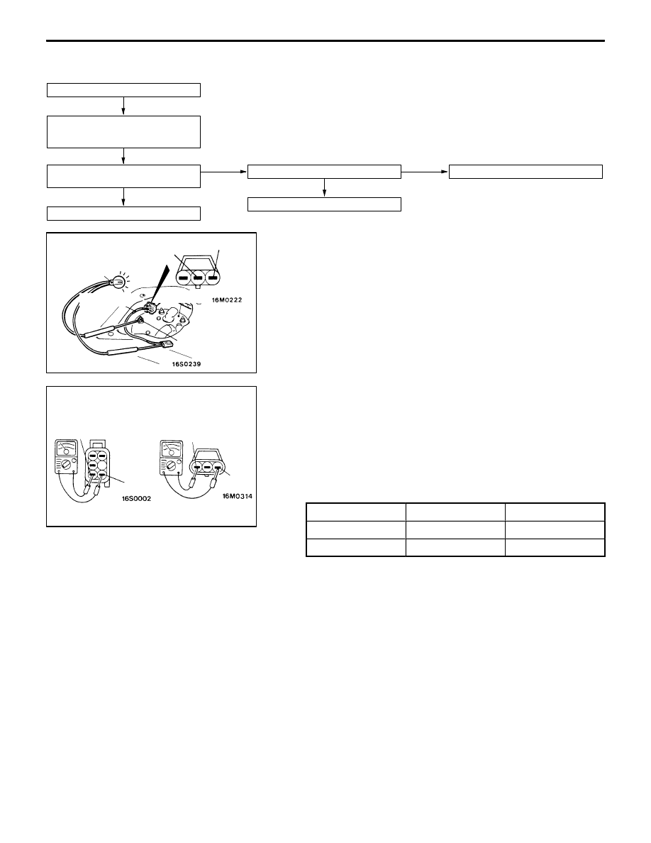
FUEL GAUGE SIMPLE CHECK

Remove the fuel gauge unit connector.

Use the special tool to connect a test
lamp (12 V – 3.4 W) to the harness
connector. (Refer to Fig.1)

When the ignition switch is turned to
ON, the test lamp illuminates.

OK

The needle of the fuel gauge moves.

OK

Replace the fuel gauge unit.

NG

Replace the fuel gauge.

NG

Repair the harness.

FUEL GAUGE UNIT CHECK

Remove the fuel gauge unit from the fuel tank.

FUEL GAUGE UNIT RESISTANCE

1.

Check that resistance value between the fuel gauge unit
terminal and earth terminal is at standard value when
fuel gauge unit float is at point F and point E.

Standard value:

Float position

Main

Sub

Point F

1.8 

±

1.2 

1.2 

±

0.8 

Point E

65.2 

±

44.8 

±

2.

Check that resistance value changes smoothly when float
moves slowly between point F and point E.

Test lamp 
(12V – 3.4W)

Earth

Fuel gauge

MB991219

Fig: 1

Earth

Fuel gauge

Fuel gauge unit

Earth

Earth

Fuel gauge unit

Main fuel gauge unit

Sub fuel gauge unit

CHASSIS ELECTRICAL – 

Combination Meters

54-29

FUEL GAUGE UNIT FLOAT HEIGHT

Move float and measure the height at point F (A) and at
point E (B) with float arm touching stopper.

Standard value:

Float position

Main

Sub

Point F

16.4

17.5

Point E

122.6

134.6

FUEL LEVEL SENSOR (THERMISTOR)

1.

Connect a test lamp (12V – 3.4W) to the fuel gauge
unit connector terminal and apply the battery voltage.

2.

Condition is good if lamp goes off when the thermistor
is immersed in water and goes on when it is taken out
of water.

ENGINE COOLANT TEMPERATURE GAUGE SIMPLE CHECK

Remove the engine coolant tempara-
ture gauge unit connector.

Connect a test lamp (12 V – 3.4 W)
between the harness side connector
and the earth.

When the ignition switch is turned to
ON, the test lamp illuminates.

OK

The needle of the engine coolant tem-
perature gauge moves.

NG

Replace the engine coolant tempera-
ture gauge.

OK

Replace the engine coolant tempera-
ture gauge unit.

NG

Repair the harness.

Point F

Point E


A

B

Stopper

Stopper

Test lamp 
(12V – 3.4 W)

Earth

Thermistor

Thermistor

Lamp goes on

Lamp goes off

CHASSIS ELECTRICAL – 

Combination Meters

54-30

ENGINE COOLANT TEMPERATURE GAUGE UNIT
CHECK

1.

Bleed the engine coolant.

2.

Remove the engine coolant temperature gauge unit.

3.

Immerse the unit in 70

_

C water to measure the resistance.

Standard value: 104 

±

13.5 

4.

After checking, apply the specified adhesive around the
thread of engine coolant temperature gauge unit. Then,
tighten the unit to the specified torque.

Specified sealant:

3M Adhesive Nut Locking No. 4171 or equivalent

5.

Add engine coolant.

COMBINATION METERS

REMOVAL AND INSTALLATION

2

1

3

Vehicle speed sensor removal
steps

D

Battery and battery tray

D

Air cleaner assembly

1. Vehicle speed sensor

Combination meter removal steps

2. Meter bezel
3. Combination meter

Thermometer

Circuit tester

10  – 12 Nm

CHASSIS ELECTRICAL – 

Combination Meters

CHASSIS ELECTRICAL – 

Combination Meters

CHASSIS ELECTRICAL – 

Combination Meters

54-31

INSPECTION

FUEL GAUGE RESISTANCE CHECK

1.

Remove the power supply tightening screw.

2.

Use a circuit tester to measure the resistance value
between the terminals.

Standard value:                              Unit: 

Measurement terminal

Resistance value

Power supply – Earth

192

±

19.2

Power supply – Fuel gauge

89

±

8.9

Fuel gauge – Earth

103

±

10.3

Caution
When inserting the testing probe into the power supply
terminal, be careful not to touch the printed board.

ENGINE COOLANT TEMPERATURE GAUGE
RESISTANCE CHECK

1.

Remove the power supply tightening screw.

2.

Use a circuit tester to measure the resistance value
between the terminals.

Standard value:                              Unit: 

Measurement terminal

Resistance value

Power supply – Earth

187

±

18.7

Power supply – Engine coolant
temperature gauge

90

±

4.5

Engine coolant temperature
gauge – Earth

247

±

24.7

Caution
When inserting the testing probe into the power supply
terminal, be careful not to touch the printed board.

VEHICLE SPEED SENSOR CHECK

1.

Connect a 3 – 10 k

 resistance as shown in the illustration.

2.

Turn the shaft of the vehicle speed sensor one turn and
check that voltage changes are caused when measured
between terminals 2 and 3 using a circuit  tester. (1 turn
= 4 pulses)

Fuel gauge

Power
supply

Earth

Earth

Power
supply

Engine
coolant
temperature
gauge

Turn

Shaft

Circuit tester

Resistance
3 – 10 k

Vehicle
speed 
sensor

Terminal No.

16R0273

Battery


Content   ..  104  105  106  107   ..