Mitsubishi Lancer Evolution VI. Manual - part 104


  Index      Mitsubishi     Mitsubishi Lancer Evolution VI - service repair manual


Search            


Content   ..  102  103  104  105   ..


Mitsubishi Lancer Evolution VI. Manual - part 104


CHASSIS ELECTRICAL – 

Ignition Switch and Immobilizer System

54-20

REMOVAL SERVICE POINTS

A

A

"

STEERING LOCK CYLINDER REMOVAL

1.

Insert the key in the steering lock cylinder and turn it
to the “ACC” position.

2.

Using a cross-tip (+) screwdriver (small) or a similar tool,
push the lock pin of the steering lock cylinder inward
and then pull the steering lock cylinder toward you.
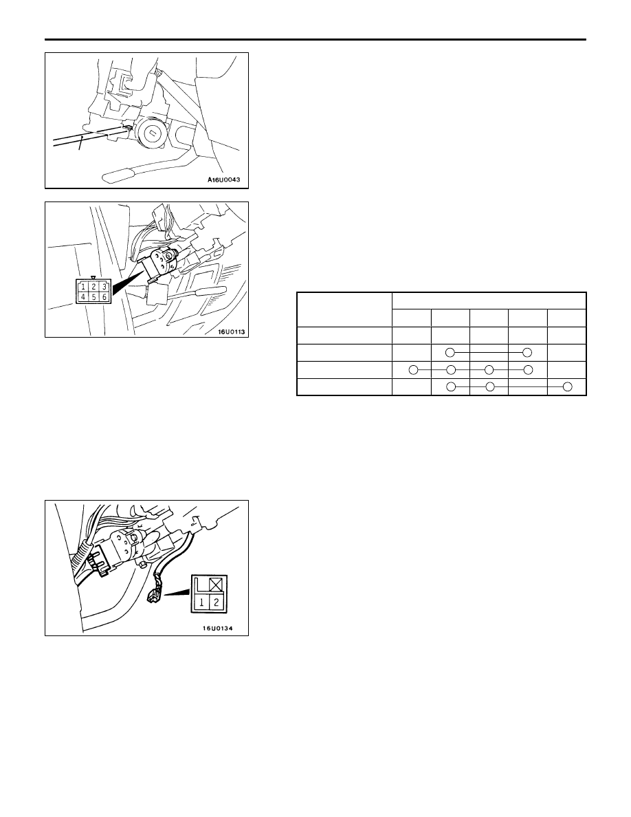
INSPECTION

IGNITION SWITCH CONTINUITY CHECK

1.

Remove the column cover lower and upper.

2.

Disconnect the wiring connector from the ignition switch.

3.

Operate the switch, and check the continuity between
the terminals.

Ignition key 

Terminal No.

Ignition key 
position

1

2

3

5

6

LOCK

ACC

ON

START

IGNITION KEY RING ANTENNA CONTINUITY CHECK

Use a circuit tester to check the continuity between the
terminals.

Cross-tip (+)
screwdriver

CHASSIS ELECTRICAL – 

Ignition Switch and Immobilizer System

54-21

ID CODE REGISTRATION METHOD

If using an ignition key that has just been newly purchased,
or if the immobilizer-ECU has been replaced, you will need
to register the ID codes for each ignition key being used
into the immobilizer-ECU. (A maximum of eight different ID
codes can be registered.)
Moreover, when the immobilizer-ECU has been replaced, you
will need to use the MUT-

II

 to register the password that

the user specifies into the immobilizer-ECU. (Refer to the
MUT-

II

 instruction manual for instructions on using the MUT-

II

.)

Caution
If registering of the ID codes is carried out all
previously-registered  codes will be erased. Accordingly,
you should have ready all of the ignition keys that have
already been registered.

1.

Connect the MUT-

II

 to the diagnosis connector.

Caution
Turn the ignition switch off before connecting or
disconnecting the MUT-

II

.

2.

Check that the diagnosis code No.54 is not displayed
for MPI system. If the code is displayed, carry out
troubleshooting  before proceeding to the next step. (Refer
to GROUP 13A – Troubleshooting).

3.

Use the ignition key that is to be registered to turn the
ignition switch to the ON position.

4.

Use the MUT-

II

 to register the ID code. If you are

registering two or more codes, use the next key to be
registered to turn the ignition switch to the ON position
without disconnecting the MUT-

II

.

5.

Disconnect the MUT-

II

. This completes the registration

operation.

6.

Check that the engine can be started by each one of
the ignition keys.

7.

Check that the diagnosis code No.54 is not displayed
for MPI system. If the code is displayed, erase it. (Refer
to GROUP 13A – Troubleshooting).

MUT-

II

CHASSIS ELECTRICAL – 

Combination Meters

CHASSIS ELECTRICAL – 

Combination Meters

54-22

COMBINATION METERS

SERVICE SPECIFICATIONS

Items

Standard value

Limit

Speedometer

Allowable indication range km/h
(Speedometer indication error to be

40

37 – 45

(Speedometer  indication error to be
with –6% to 

+

10%)

80

75 – 88

)

120

113 – 132

160

150 – 176

Pointer fluctuation km/h (at vehicle speeds of higher than 35
km/h)

±

3

Tachometer indica-
tion error r/min

700

All types of tachometer

±

100

tion error r/min

3,000

Meters measurable up to 6,000 rpm and
meters measurable up to 8,000 rpm

150

Meters measurable up to 9,000 rpm and
meters measurable up to 10,000 rpm

225

– 100

4,750

Meters measurable up to 6,000 rpm

±

160

5,000

Meters measurable up to 8,000 rpm

±

250

Meters measurable up to 9,000 rpm and
meters measurable up to 10,000 rpm

325

– 125

6,000

Meters measurable up to 8,000 rpm

±

300

7,000

Meters measurable up to 9,000 rpm and
meters measurable up to 10,000 rpm

400

– 100

8,000

Meters measurable up to 10,000 rpm

400

– 0

Fuel gauge unit
resistance

Main tank

Float point F

1.8 

±

1.2

resistance 

Float point E

65.2 

±

4

Sub tank

Float point F

1.2 

±

0.8

Float point E

44.8 

±

3

Fuel gauge unit
float height mm

Main tank

Float point F

16.4

float height mm

Float point E

122.6

Sub tank

Float point F

17.5

Float point E

134.6

Engine coolant temperature gauge unit resistance (at 70 

_

C) 

104 

±

13.5

Fuel gauge resis-
tance

Power supply and earth

192 

±

19.2

tance 

Power supply and fuel gauge

89 

±

8.9

Fuel gauge and earth

103 

±

10.3

Engine coolant
temperature gauge

Power supply and earth

187 

±

18.7

temperature gauge
resistance 

Power supply and engine coolant temperature gauge

90 

±

4.5

Engine coolant temperature gauge and earth

247 

±

24.7

CHASSIS ELECTRICAL – 

Combination Meters

54-23

SEALANT

Items

Specified sealant

Remark

Engine coolant temperature gauge
unit threaded portion

3M Adhesive nut locking No. 4171 or
equivalent

Drying sealant

SPECIAL TOOLS

Tool

Number

Name

Use

A

B

C

D

MB991223
A:

MB991219

B:

MB991220

C:

MB991221

D:

MB991222

Harness set
A:

Test harness

B:

LED harness

C:

LED harness
adapter

D:

Probe

Fuel gauge simple check
A:

Connector pin contact pressure check

B, C: Power circuit check
D:

Commercial tester connection


Content   ..  102  103  104  105   ..