Mitsubishi Lancer Evolution VI. Manual - part 89


  Index      Mitsubishi     Mitsubishi Lancer Evolution VI - service repair manual


Search            


Content   ..  87  88  89  90   ..


Mitsubishi Lancer Evolution VI. Manual - part 89


SRS – 

General Information

52B-2

GENERAL INFORMATION

To improve safety, the SRS is available as optional
part.
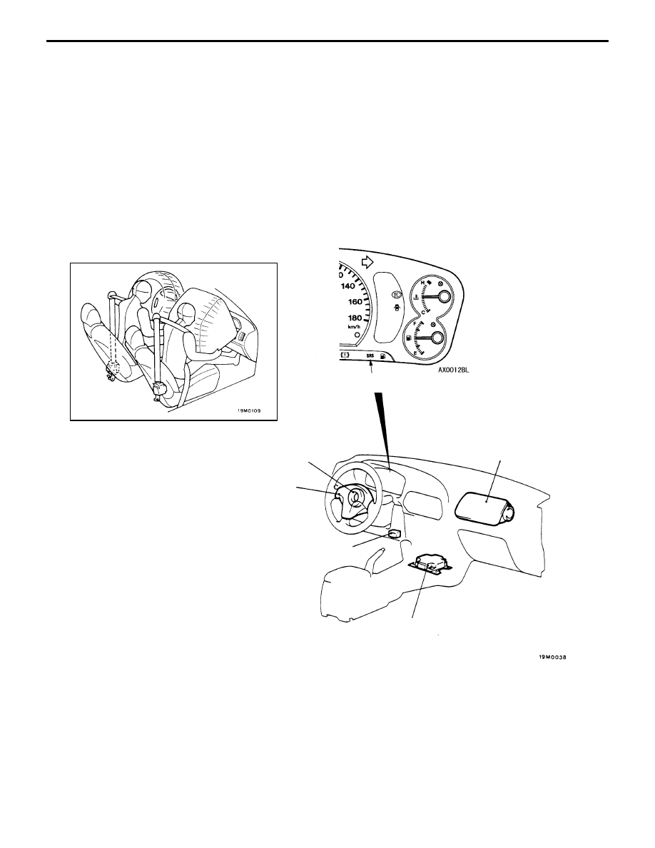
The SRS consists of two air bag modules, SRS
air bag control unit (SRS-ECU), SRS warning lamp
and clock spring. One air bag is located in the
centre of the steering wheel and another above
the glove box. Each air bag has a folded air bag
and an inflator unit. The control unit under the floor
console monitors the system and has a safing G
sensor and an analog G sensor. The warning lamp
on the instrument panel indicates the operational

status of the SRS. The clock spring is installed
in the steering column.
Only authorized service personnel should do work
on or around the SRS components. Those service
personnel should read this manual carefully before
staring any such work. Extreme care must be used
when servicing the SRS to avoid injury to the service
personnel (by inadvertent deployment of the air
bags) or the driver (by rendering the SRS
inoperative).

Air bag module
(Driver’s side)

Clock spring

Air bag module 
(Front passenger’s side)

Diagnosis
connector

SRS-ECU

SRS warning lamp

SRS  – 

SRS Service Precautions

52B-3

SRS SERVICE PRECAUTIONS

1.

In order to avoid injury to yourself or others
from accidental deployment of the air bag during
servicing, read and carefully follow all the
precautions and procedures described in this
manual.

2.

Do not use any electrical test equipment on
or near SRS components, except those
specified on P.52B-5.

3.

Never Attempt to Repair the Following
Components:

D

SRS air bag control unit (SRS-ECU)

D

Clock Spring

D

Air Bag Module 
(Driver‘s side or front passenger’s side*)

NOTE
*: Vehicles with front passenger’s air bag
If any of these components are diagnosed as
faulty, they should only be replaced, in
accordance with the INDIVIDUAL COM-
PONENT SERVICE procedures in this manual,
starting at page 52B-22.

4.

After disconnecting the battery cable, wait 60 seconds
or more before proceeding with the following work.
The SRS system is designed to retain enough voltage
to deploy the air bag for a short time even after the
battery has been disconnected, so serious injury may
result from unintended air bag deployment if work
is done on the SRS system immediately after the
battery cables are disconnected.

5.

Do not attempt to repair the wiring harness connectors
of the SRS. If any of the connectors are diagnosed as
faulty, replace the wiring harness. If the wires are
diagnosed as faulty, replace or repair the wiring harness
according to the following table.

Battery

Insulating tape

SRS-ECU connector

SRS  – 

SRS Service Precautions

52B-4

SRS-ECU
terminal No.

Harness connector
(No. of terminals,
colour)

Destination of harness

Corrective action

1 to 4

21 pins, yellow

5

Body wiring harness 

 Clock spring 

 Air bag

module (Driver’s side)

Correct or replace each
wiring harness

Replace

6

module (Driver’s side)

wiring  harness.  Replace
clock spring.

7*

Body wiring harness 

 Air bag module (Front

passenger’s side)

Correct or replace each
wiring harness

8*

passenger’s side)

wiring harness.

9,10

11

Body wiring harness 

 Diagnosis connector

Correct or replace each
wiring harness.

12

13

Body wiring harness 

 Junction block (fuse No.2)

Correct or replace each
wiring harness

14

Body wiring harness 

 Junction block (fuse No.4)

wiring harness.

15

Body wiring harness 

 SRS warning lamp

16 to 19

20

Body wiring harness 

 Earth

Correct or replace each
wiring harness.

21

NOTE
*: Vehicles with front passenger’s air bag

6.

SRS components should not be subjected to hear over 93

_

C, so remove the SRS-ECU, air bag

module and clock spring before drying or baking the vehicle after painting.

7.

Whenever you finish servicing the SRS, check warning lamp operation to make sure that the system
functions properly. (Refer to P.52B-14.)

8.

Make certain that the ignition switch is LOCK (OFF) position when the MUT-

II

 is connected or

disconnected.

9.

If you have any questions about the SRS, please contact your local distributor.

NOTE
SERIOUS INJURY CAN RESULT FROM UNINTENDED AIR BAG DEPLOYMENT, SO USE ONLY
THE PROCEDURES AND EQUIPMENT SPECIFIED IN THIS MANUAL.

SRS  – 

Special Tools / Test Equipment

52B-5

SPECIAL TOOLS

Tool

Number

Name

Use

MB991502

MUT

-II

 sub 

assembly

D

Reading diagnosis codes

D

Erasing diagnosis code

D

Reading trouble period

D

Reading erase times

MB991613

SRS check 
harness

Checking the SRS electrical circuitry

MB990803

Steering wheel 
puller

Steering wheel removal

MB686560

SRS air bag 
adapter harness A

D

Deployment of air bag modules and seat
belt with pre-tensioner inside the vehicle

D

Deployment of air bag module (front
passenger’s side) outside the vehicle

MR203491 or
MB628919

SRS air bag 
adapter harness B

Deployment of air bag module (driver’s side)
outside the vehicle

TEST EQUIPMENT

Tool

Name

Use

Digital multi-meter

Checking the SRS electrical circuitry

Use a multi-meter for which the
maximum test current is 2 mA or less
at the minimum range of resistance
measurement


Content   ..  87  88  89  90   ..