Mitsubishi Lancer Evolution VI. Manual - part 90


  Index      Mitsubishi     Mitsubishi Lancer Evolution VI - service repair manual


Search            


Content   ..  88  89  90  91   ..


Mitsubishi Lancer Evolution VI. Manual - part 90


SRS  – 

Troubleshooting

52B-6

TROUBLESHOOTING

STANDARD FLOW OF DIAGNOSTIC TROUBLESHOOTING

Refer to GROUP 00 – How to Use Troubleshooting/Inspection  Service  Points.

DIAGNOSIS FUNCTION

DIAGNOSIS CODES CHECK

Connect the MUT-

II

 to the diagnosis connector (16-pin) under the instrument under cover, then check

diagnosis codes.
(Refer to GROUP 00 – How to Use Troubleshooting/Inspection  Service  Points.)

ERASING DIAGNOSIS CODES

Connect the MUT-

II

 to the diagnosis connector and erase the diagnosis code.

Caution
Turn off the ignition switch before connecting or disconnecting the MUT-

II

.

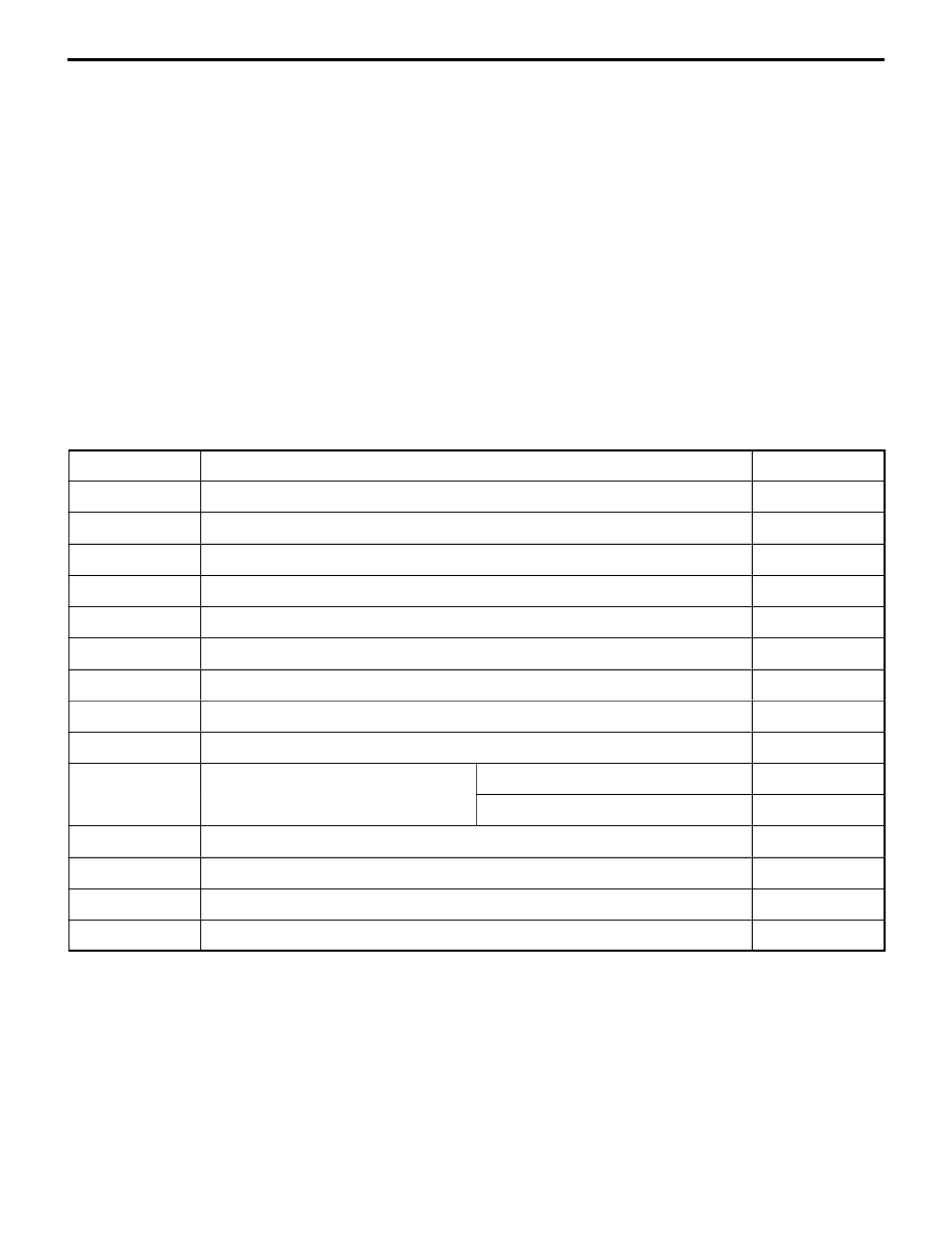
INSPECTION CHART FOR DIAGNOSIS CODES

Inspect according to the inspection chart that is appropriate for the malfunction code.

Code No.

Diagnosis item

Reference page

14

Analog G-sensor system in the SRS-ECU

52B-7

15,16

Safing G-sensor system in the SRS-ECU

52B-7

21, 22, 61, 62

Driver’s side air bag module (squib) system

52B-8

24, 25, 64, 65

Front passenger’s side air bag module (squib) system

52B-9

31, 32

SRS-ECU capacitor system

52B-9

34*

Connector lock system

52B-10

35

SRS-ECU (deployed air bag) system

52B-10

41*

IG

1

 (A) power circuit system

52B-10

42*

IG

1

 (B) power circuit system

52B-11

43

SRS warning lamp drive circuit
system

Lamp does not illuminate.*

52B-12

system

Lamp does not switch off.

52B-12

44

SRS warning lamp drive circuit system

52B-13

45

SRS-ECU non-volatile memory (EEPROM) and A/D converter system

52B-13

51, 52

Driver’s side air bag module (squib ignition drive circuit) system

52B-13

54, 55

Front passenger’s side air bag module (squib ignition drive circuit) system

52B-13

NOTE
(1) *: If the vehicle condition returns to normal, the diagnosis code will be automatically erased, and the SRS warning

lamp will return to normal.

(2) If the vehicle has a discharged battery it will store the fault codes 41 or 42. When these diagnosis codes are

displayed, check the battery.

SRS  – 

Troubleshooting

52B-7

INSPECTION PROCEDURE CLASSIFIED BY DIAGNOSIS CODE

Code No.14 Analog G-sensor system in the SRS-ECU

Probable cause

The SRS-ECU monitors the output of the analog G-sensor inside the SRS-ECU.
It outputs this code when any of the following are detected.

D

When the analog G-sensor is not operating

D

When the characteristics of the analog G-sensor are abnormal

D

When the output from the analog G-sensor is abnormal

D

Malfunction of SRS-ECU

Replace the SRS-ECU.

Code No.15, 16 Safing G-sensor system in the SRS-ECU

Probable cause

This code is output if there is a short or open circuit between the terminals of the
safing G-sensor inside the SRS-ECU.
The trouble causes for each diagnosis code No. are as follows.

D

Malfunction of SRS-ECU

Code No.

Trouble symptom

15

Short circuit in the safing G-sensor

16

Open circuit in the safing G-sensor

Replace the SRS-ECU.

SRS  – 

Troubleshooting

52B-8

Code No.21, 22, 61 or 62 Driver’s side air bag module
(squib) system

Probable cause

These diagnosis codes are output if there is abnormal resistance between the input
terminals of the driver’s side air bag module (squib).
The trouble causes for each diagnosis code No. are as follows.

D

Malfunction of clock spring

D

Partial disconnection due to incorrect clock spring
neutral position

D

Malfunction of wiring harnesses or connectors

D

Malfunction of driver’s side air bag module (squib)

D

Malfunction of SRS-ECU

Code No.

Trouble symptom

21

D

Short in driver’s side air bag module (squib) or harness short

D

Short in clock spring

D

Malfunction of connector*

22

D

Open circuit in driver’s side air bag module (squib) or open harness

D

Open circuit in clock spring

D

Malfunction of connector contact

61

D

Short in driver’s side air bag module (squib) harness leading to the power supply

62

D

Short in driver’s side air bag module (squib) harness leading to the earth

NOTE
*:

The connector in the squib circuit has a built-in short bar which short-circuits between plus (+) lead and minus
(–) lead of the squib circuit when the connector is not being connected to prevent an accidental air bag deployment
possibly caused by static electricity, etc. Therefore, malfunction of the connector can also be caused by this
short bar which fails to be released even when the connector is reconnected if it is damaged.

MUT-

II

 Self-diag code

D

Disconnect clock spring
connector B-82.

D

Connect SRS check har-
ness connector (1).

D

Erase diagnosis code
memory.
Are code Nos.21, 22, 61 or
62 output?

Yes

Check the following
connectors:
B-82, B-51

NG

Repair

OK

Check trouble symptoms.

NG

Check the harness wire
between the SRS-ECU
and clock spring.

NG

Repair

OK

Replace the SRS-ECU.

No

Check the clock spring. (Refer to P.52B-30.)

NG

Repair

OK

Replace the driver’s side air bag module.

SRS check harness
(MB991613)

Body wiring
harness

Clock spring

1

SRS  – 

Troubleshooting

52B-9

Code No.24, 25, 64 or 65 Front passenger’s side air bag
module (squib) system

Probable cause

These diagnosis codes are output if there is abnormal resistance between the input
terminals of the driver’s side air bag module (squib).
The trouble causes for each diagnosis code No. are as follows.

D

Malfunction of wiring harnesses or connectors

D

Malfunction of front passenger’s side air bag module
(squib)

D

Malfunction of SRS-ECU

Code No.

Trouble symptom

24

D

Short in front passenger’s side air bag module (squib) or harness short

D

Malfunction of connector*

25

D

Open circuit in front passenger’s side air bag module (squib) or open harness

D

Malfunction of connector contact

64

D

Short in front passenger’s side air bag module (squib) harness leading to the power
supply

65

D

Short in front passenger’s side air bag module (squib) harness leading to the earth

NOTE
*:

The connector in the squib circuit has a built-in short bar which short-circuits between plus (+) lead and minus
(–) lead of the squib circuit when the connector is not being connected to prevent an accidental air bag deployment
possibly caused by static electricity, etc. Therefore, malfunction of the connector can also be caused by this
short bar which fails to be released even when the connector is reconnected if it is damaged.

OK

Check trouble symptoms.

NG

Check the harness wire
between the front passen-
ger’s side air bag module
(squib) and SRS-ECU.

NG

Repair

OK

Replace the SRS-ECU.

Yes

Check the following
connectors:
B-01, B-51

NG

Repair

SRS check harness
(MB991613)

Body
wiring
harness

1

No

Replace the front passenger’s side air bag module.

MUT-

II

 Self-diag code

D

Disconnect front 
passenger’s side air bag
module connector B-01.

D

Connect SRS check 
harness connector (1).

D

Erase diagnosis code
memory.

Are code Nos.24, 25, 64 or 65
output?

Code No.31 or 32 SRS-ECU capacitor system

Probable cause

Probable cause
These diagnosis codes are output if there is abnormal resistance between the input
terminals of the driver’s side air bag module (squib).

D

Malfunction of SRS-ECU

Code No.

Trouble symptom

31

D

Voltage at the capacitor terminal is higher than the specified value for five seconds
or more

32

D

Voltage at the capacitor terminal is lower than the specified value for five seconds
or more (this is not detected if diagnosis code No.41 or 42 indicating system voltage
drop has been output.)

Replace the SRS-ECU.


Content   ..  88  89  90  91   ..