Mitsubishi Lancer Evolution VI. Manual - part 88
EXTERIOR –
Marks
51-8
MARKS
REMOVAL AND INSTALLATION
2
1
3
"
A
A
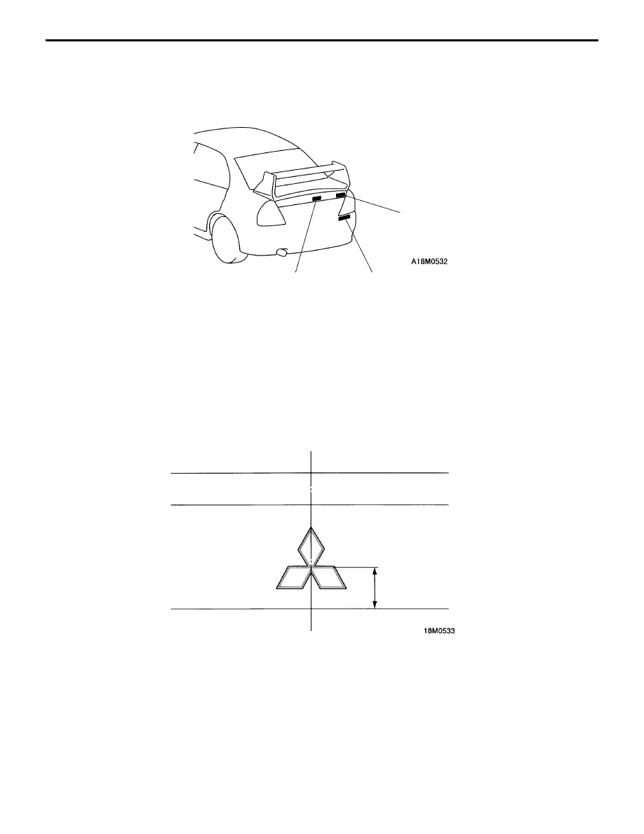
1. Three-diamond mark
"
A
A
2. EVOLUTION-VI mark
"
A
A
3. LANCER mark
INSTALLATION SERVICE POINT
"
A
A
MARK INSTALLATION
Mounting Positions
1.
Three-diamond mark
Center of vehicle
44 mm