Mitsubishi Lancer Evolution VI. Manual - part 15
ENGINE –
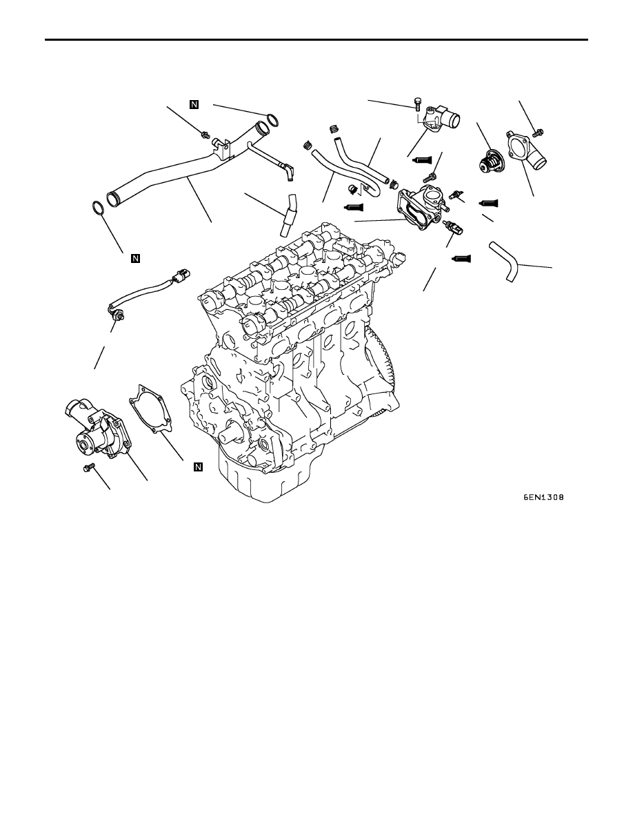
Water Pump and Water Hose
11-35
REMOVAL AND INSTALLATION <EVOLUTION IV or V>
1
2
3
4
5
6
7
8
9
11
12
13
14
15
16
14 Nm
22 Nm
11 Nm
24 Nm
24 Nm
29 Nm
13 Nm
10
13 Nm
Removal steps
1. Water hose
2. Water hose
3. Water hose
4. Water hose
"
E
A
5. Water temperature sensor
"
D
A
6. Water temperature gauge unit
7. Water inlet fitting
8. Thermostat
"
C
A
9. Water outlet fitting
"
B
A
10. Thermostat housing
"
A
A
11. O-ring
"
A
A
12. Water inlet pipe
"
A
A
13. O-ring
14. Water pump
15. Water pump gasket
16. Knock sensor