Mitsubishi Lancer Evolution VI. Manual - part 13


  Index      Mitsubishi     Mitsubishi Lancer Evolution VI - service repair manual


Search            


Content   ..  11  12  13  14   ..


Mitsubishi Lancer Evolution VI. Manual - part 13


ENGINE  – 

Fuel and Emission Control Parts

11-27

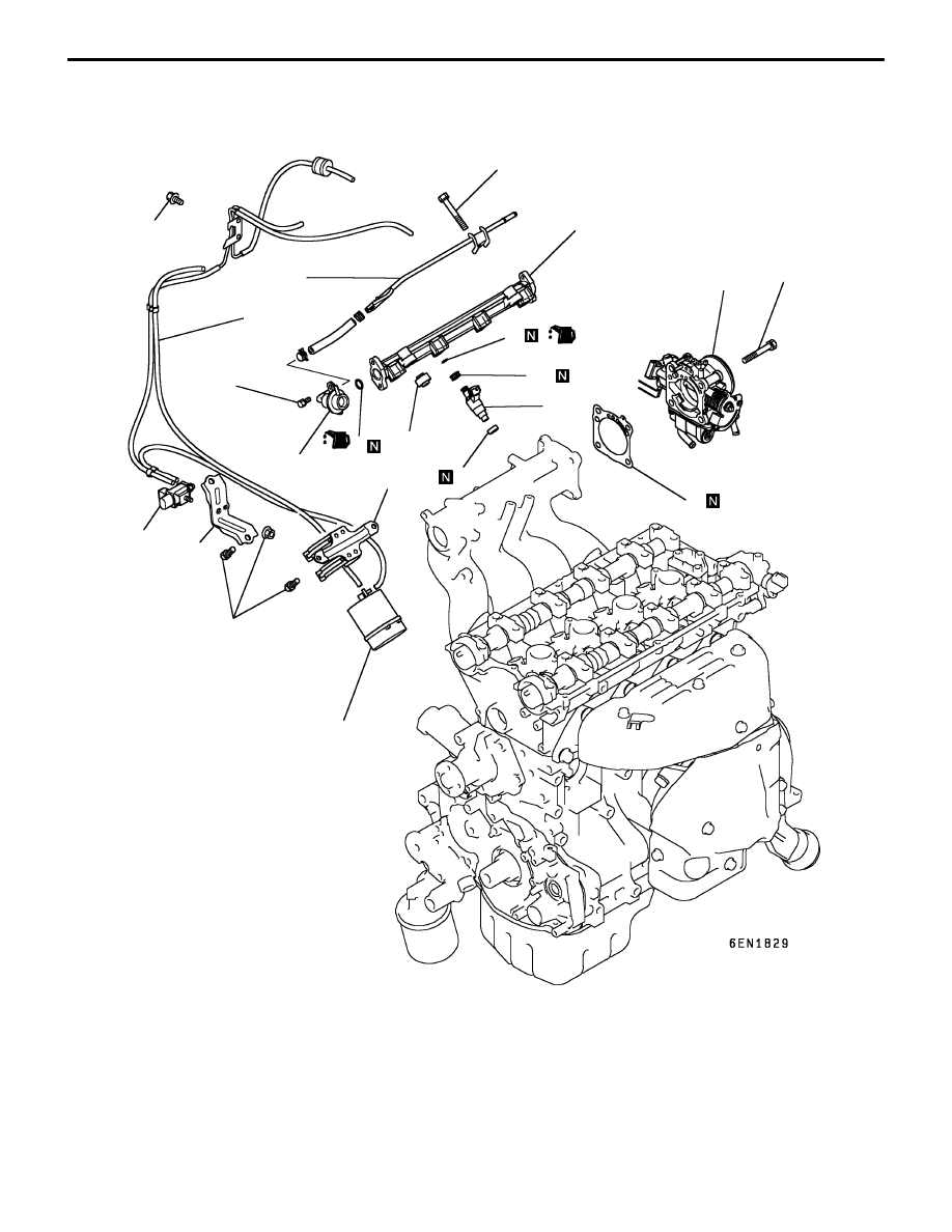
FUEL AND EMISSION CONTROL PARTS

REMOVAL AND INSTALLATION

1

2

3

4

5

6

7

8

9

10

11

12

13

14

15

16

 9 Nm

 11 Nm

 9 Nm

 11 Nm

 18 Nm

Removal steps

1. Throttle body

"

C

A

2. Throttle body gasket
3. Fuel return pipe

"

B

A

4. Fuel pressure regulator
5. O-ring
6. Insulator
7. Insulator

"

A

A

8. Injector

9. O-ring

10. Grommet

11. Delivery pipe

12. Vacuum hose and vacuum pipe
13. Vacuum tank
14. Vacuum tank bracket
15. Solenoid valve
16. Solenoid valve bracket

ENGINE  – 

Fuel and Emission Control Parts

11-28

INSTALLATION SERVICE POINTS

"

A

A

INJECTORS INSTALLATION

(1) Before installing an injector, the rubber O-ring must be

lubricated with a drop of clean engine oil to aid in
installation.

(2) Install injector top end. Be careful not to damage O-ring

during installation.

"

B

A

FUEL PRESSURE REGULATOR INSTALLATION

(1) Apply a small amount of new engine oil to the O-ring.

Insert the fuel pressure regulator into the delivery pipe
being careful not to damage the O-ring.

Caution
Be sure not to let engine oil get into the delivery
pipe.

(2) Check that the fuel pressure regulator turns smoothly.

If it does not turn smoothly, the O-ring may be trapped.
Remove the fuel pressure regulator and check the O-ring
for damage, and then re-insert it into the delivery pipe
and check once again.

"

C

A

GASKET INSTALLATION

Position the projection as shown in the illustration.

1EN0388

Grommet

O-ring

Projection

ENGINE  – 

Secondary Air System and Intake Manifold

11-29

SECONDARY AIR SYSTEM AND INTAKE MANIFOLD

REMOVAL AND INSTALLATION

1

2

3

4

5

6

7

8

9

10

11

 11 Nm

 35 Nm

 24 Nm

 11 Nm

 19 Nm

 30 Nm

 35 Nm

 24 Nm

 49 Nm

 21 Nm

 13 Nm

 21 Nm

 35 Nm

Removal steps

1. Exhaust manifold heat protector
2. Vacuum hose and vacuum pipe

"

B

A

3. Air pipe assembly
4. Air control valve gasket
5. Air control valve assembly
6. Engine hanger

"

A

A

7. Air control valve bracket
8. Intake manifold stay
9. Alternator brace stay

10. Intake manifold

11. Intake manifold gasket

ENGINE  – 

Secondary Air System and Intake Manifold

11-30

INSTALLATION SERVICE POINTS

"

A

A

AIR CONTROL VALVE BRACKET INSTALLATION

(1) Attach the air control valve bracket and the engine hanger

to the intake manifold using bolts and nuts with which
the intake manifold is also installed to the engine.

(2) Tighten the bolts and nuts to the specified torque in the

sequence given in the illustration.

"

B

A

AIR PIPE ASSEMBLY INSTALLATION

(1) Install the air pipe assembly to the exhaust manifold and

to the air control valve and secure it provisionally by
tightening the fasteners handtight.

(2) Tighten the fasteners to the specified torque in the

sequence given in the illustration.

(3)

(2)

(1)

(3)

(2)

(1)

(4)


Content   ..  11  12  13  14   ..