Mitsubishi Lancer Evolution VI. Manual - part 11


  Index      Mitsubishi     Mitsubishi Lancer Evolution VI - service repair manual


Search            


Content   ..  9  10  11  12   ..


Mitsubishi Lancer Evolution VI. Manual - part 11


ENGINE  – 

Timing Belt

11-19

"

D

A

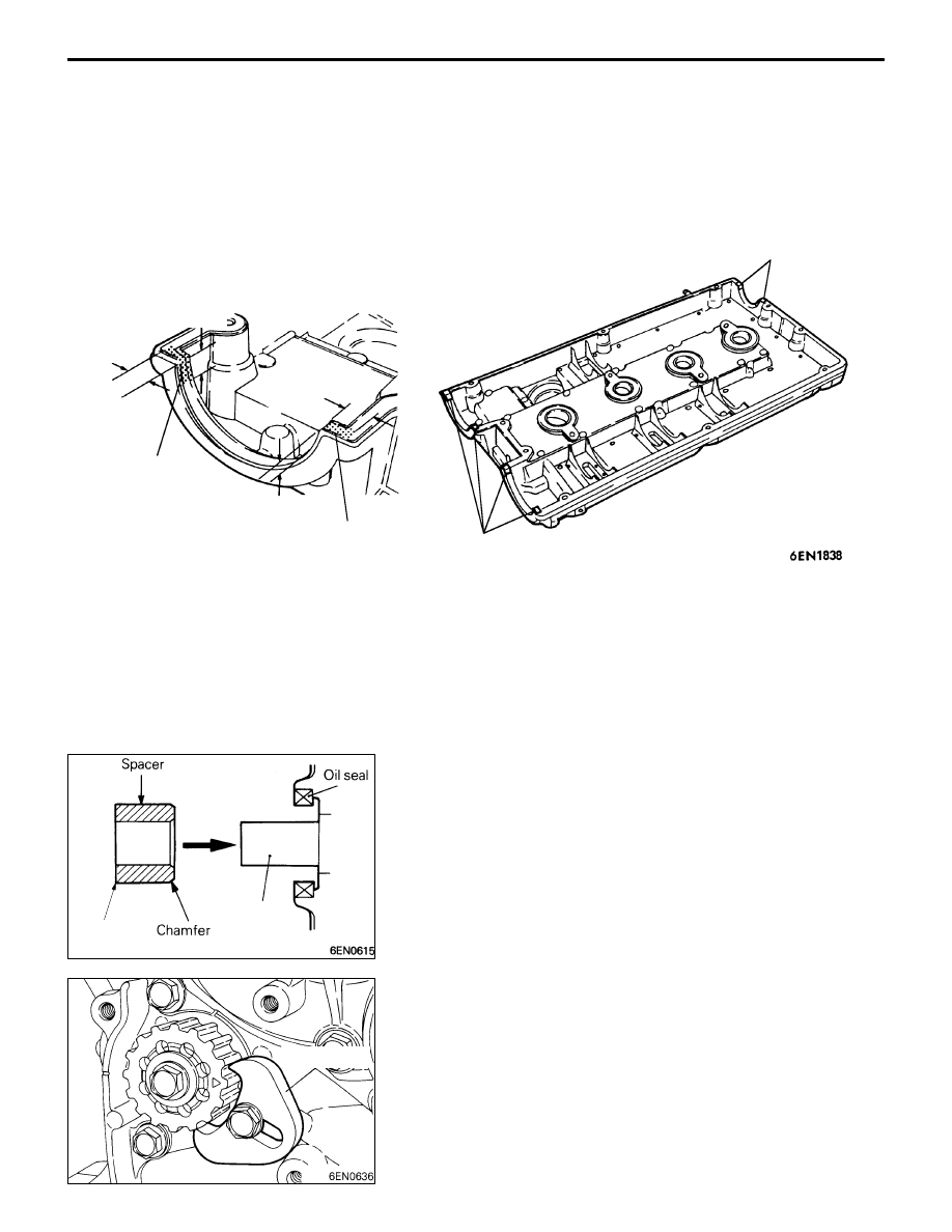
SEALANT APPLICATION TO ROCKER COVER

Apply sealant to the areas indicated in the illustration.

Specified sealant: 3M

TM

 AAD Part No. 8672 or equivalent

Apply sealant

Apply sealant

Apply sealant

10 mm

10 mm

10 mm

10 mm

Apply sealant

"

E

A

SPACER INSTALLATION

Install the spacer with the chamfered end toward the oil seal.

"

F

A

COUNTERBALANCE SHAFT SPROCKET
INSTALLATION

(1) Install the counterbalance shaft sprocket and screw the

bolt.

(2) Install special tool MD998785 as shown in the illustration

to lock the counterbalance shaft.

(3) Tighten the bolt, and then remove the special tool.

Counter-
balance
shaft

Sharp
edge

MD998785

ENGINE  – 

Timing Belt

11-20

"

G

A

TIMING BELT “B” INSTALLATION

(1) Align timing marks on the crankshaft sprocket “B” and

counterbalance  shaft sprocket with the marks on the front
case respectively.

(2) Install the timing belt “B” on the crankshaft sprocket “B”

and counterbalance shaft sprocket. There should be no
slack on the tension side.

(3) Make sure that the relationship between the tensioner

pulley center and the bolt center is as shown in the
illustration.

(4) Move the tensioner “B” in the direction of arrow while

lifting with a finger to give a sufficient tension to the tension
side of timing belt. In this condition, tighten bolt to secure
tensioner  “B”. When the bolt is tightened, use care to
prevent shaft from turning together. If shaft is turned
together, belt will be overtensioned.

(5) Check to ensure that timing marks on sprockets and front

case are in alignment.

(6) Press with index finger the center of span on the tension

side of timing belt “B”. The bolt must deflect 5 – 7 mm.

"

H

A

CRANKSHAFT BOLT TIGHTENING

(1) Using the special tool, hold the flywheel or drive plate.
(2) Install the crankshaft pulley in position.

Timing
marks

Timing
marks
(on front
case)

ENGINE  – 

Timing Belt

11-21

"

I

A

OIL PUMP SPROCKET INSTALLATION

(1) Insert a Phillips screwdriver (shank diameter 8 mm shaft)

through the plug hole on the left side of the cylinder
block to block the left counterbalance shaft.

(2) Install the oil pump sprocket.
(3) Apply a proper amount of engine oil to the bearing surfaces

of the nuts.

(4) Tighten the nuts to the specified torque.

"

J

A

AUTO TENSIONER INSTALLATION

(1) If the auto tensioner rod is in its fully extended position,

reset it as follows.

(2) Clamp the auto-tensioner in the vise with soft jaws.
(3) Push in the rod little by little with the vise until the set

hole A in the rod is aligned with the hole B in the cylinder.

(4) Insert a wire (1.4 mm in diameter) into the set holes.
(5) Unclamp the auto tensioner from the vise.

(6) Install the auto tensioner to front case and tighten to

the specified torque.

Caution
Leave the wire installed in the auto tensioner.

"

K

A

TENSIONER PULLEY INSTALLATION

Install the tensioner pulley in such direction that its two small
holes are arranged vertically.

6EN0564

A

B

6EN1323

Small holes

ENGINE  – 

Timing Belt

11-22

"

L

A

TIMING BELT INSTALLATION

(1) Place the exhaust side camshaft sprocket in a position

where its timing mark is one tooth offset from the timing
mark on the rocker cover in the counterclockwise direction.

NOTE
Even if the timing marks on the sprocket and the rocker
cover are brought into alignment, the exhaust camshaft
is forced back by the valve spring tension. It is stabilized
at a position one tooth before the timing mark.

(2) Align the timing mark on the intake side camshaft sprocket

with that on the rocker cover.

NOTE
Even if the timing marks on the sprocket and the cover
are brought into alignment, the intake camshaft is forced
to turn one tooth in the clockwise direction by the valve
spring tension and stabilized there.

(3) Place the timing mark on the crankshaft sprocket one

tooth this side from the mated timing mark as in the case
of the camshaft sprocket.

(4) Align the timing mark on oil pump sprocket with its mating

mark.

(5) Remove the plug on cylinder block and insert a Phillips

screwdriver (shank diameter 8 mm) through the hole
(Engine with counterbalance shafts).
If it can be inserted as deep as 60 mm or more,  the
timing marks are correctly aligned. If the inserted depth
is only 20 – 25 mm, turn the oil pump sprocket one turn
and realign timing marks. Then check to ensure that the
screwdriver can be inserted 60 mm or more. Keep the
screwdriver inserted until installation of timing belt is
finished.

Timing mark

Timing mark

6EN1327

Oil pump 
sprocket 
timing marks

Screwdriver

6EN1026

Plug


Content   ..  9  10  11  12   ..