Mitsubishi Eclipse / Eclipse Spyder (2000-2002). Service and repair manual - part 625
 

  Index      Mitsubishi     Mitsubishi Eclipse / Eclipse Spyder (2000-2002). Service and repair manual


Search            


Content   ..  623  624  625  626   ..


Mitsubishi Eclipse / Eclipse Spyder (2000-2002). Service and repair manual - part 625


DOOR

TSB Revision

BODY

42-47

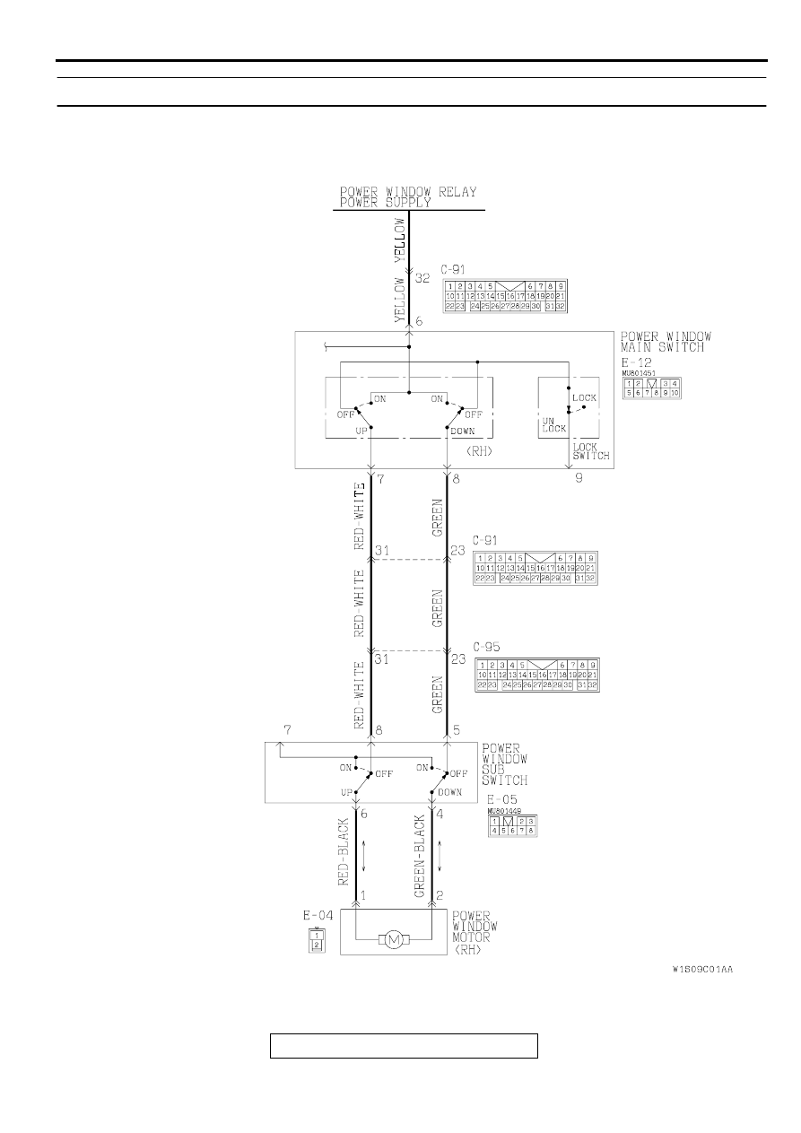
INSPECTION PROCEDURE 2: Only the door window <RH> does not open and close.

AC03728

Power Window Motor <RH> Drive Circuit

<ECLIPSE>

AB

DOOR

TSB Revision

BODY

42-48

AC03736

:

AB

<ECLIPSE SPYDER>

DOOR

TSB Revision

BODY

42-49

CIRCUIT OPERATION

•

When the power window switch is operated up or 
down, the power window motor operates and 
opens or closes the door window.

TECHNICAL DESCRIPTION (COMMENT)

•

The cause may be a malfunction of the power 
window motor <RH> drive circuit.

TROUBLESHOOTING HINTS

•

Malfunction of the power window main switch

•

Malfunction of the power window sub-switch

•

Malfunction of the power window motor <RH>

•

Damaged harness wires or connectors

AC001991AK

CONNECTOR: C-91

CONNECTOR 
BLOCK (LH)

AC001992AG

CONNECTOR: C-95

CONNECTOR 
BLOCK (RH)

AC001794

E-12

CONNECTOR: E-12

<DRIVER'S SIDE>

AC

AC001795

E-04

E-05

CONNECTORS: E-04, E-05

<PASSENGER'S SIDE>

AB

DOOR

TSB Revision

BODY

42-50

DIAGNOSIS

STEP 1. Check the power window main switch continuity.
(1) Remove the power window main switch. (Refer to 

P.42-71

.)

(2) Check the continuity when the power window main switch 

<RH> is turned to the UP position or DOWN position.

Q: Is the power window main switch damaged?

YES : Replace it, then go to Step 6.
NO :  Go to Step 2.

STEP 2. Check the power window sub-switch continuity.
(1) Remove the power window sub-switch. (Refer to 

P.42-71

.)

(2) Check the continuity when the power window sub-switch is 

turned to the UP position or DOWN position.

Q: Is the power window sub-switch damaged?

YES : Replace it, then go to Step 6.
NO :  Go to Step 3.

FRONT <RH> SWITCH 
POSITION

TESTER 
CONNECTION

SPECIFIED 
CONDITION

When the lock 
switch is 
locked.

UP

6 

−

 7

Continuity

OFF

7 

−

 8

Continuity

DOWN

6 

−

 8

Continuity

When the lock 
switch is
unlocked.

UP

6 

−

 7, 8 

−

 9

Continuity

OFF

7 

−

 8 

−

 9

Continuity

DOWN

6 

−

 8, 7 

−

 9

Continuity

AC000463

1 2

3 4

5 6 7 8 9 10

AB

<ECLIPSE>

AC003390

1 2

3 4

5 6 7 8 9 10

<ECLIPSE SPYDER>

AB

 SWITCH 
POSITION

TESTER 
CONNECTION

SPECIFIED 
CONDITION

UP

4 

−

 5, 6 

−

 7

Continuity

OFF

4 

−

 5, 6 

−

 8

Continuity

DOWN

6 

−

 8, 4 

−

 7

Continuity

AC000464

1

2 3

4 5 6 7 8


Content   ..  623  624  625  626   ..