Mitsubishi Eclipse / Eclipse Spyder (2000-2002). Service and repair manual - part 571


  Index      Mitsubishi     Mitsubishi Eclipse / Eclipse Spyder (2000-2002). Service and repair manual


Search            


Content   ..  569  570  571  572   ..


Mitsubishi Eclipse / Eclipse Spyder (2000-2002). Service and repair manual - part 571


MASTER CYLINDER ASSEMBLY AND BRAKE BOOSTER

TSB Revision

BASIC BRAKE SYSTEM

35A-33

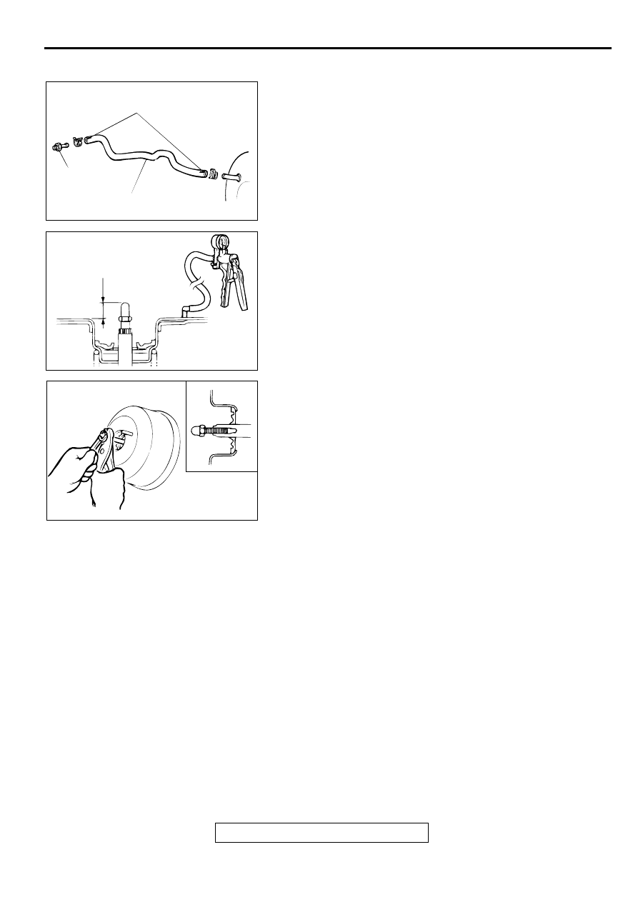
INSTALLATION SERVICE POINTS

>>A<< VACUUM HOSE CONNECTION
1. Install the vacuum hose with the white-marked sections 

facing up.

2. Insert securely and completely until the vacuum hose at the 

engine side contacts the edge of the hexagonal part of the 
fitting, and then secure with the hose clamp.

>>B<< CLEARANCE ADJUSTMENT BETWEEN BRAKE 
BOOSTER PUSHROD AND PRIMARY PISTON
1. Using a hand vacuum pump, apply a negative pressure of 

66.7 kPa (19.6 inHg) to the brake booster.

2. Measure protruding length A at the pushrod.

Standard value (A): 10.28 

 10.53 mm (0.404 

 0.415 

inch)

3. If the protruding length is not within the standard value 

range, adjust by changing the pushrod length by turning the 
end of the pushrod.

AC000899

WHITE MARKS

FITTING

VACUUM HOSE

AB

AC000900 AB

A

AC000901

MASTER CYLINDER ASSEMBLY AND BRAKE BOOSTER

TSB Revision

BASIC BRAKE SYSTEM

35A-34

MASTER CYLINDER

M1351004200063

DISASSEMBLY AND ASSEMBLY

CAUTION

Do not disassemble the primary piston and secondary piston assembly.

DISASSEMBLY SERVICE POINT

<<A>> PISTON STOPPER RING DISASSEMBLY
Remove the piston stopper ring while depressing the piston.

AC000902

2

3

1

4

6

7

5

11

10

N

9

N

8

N

10

9

8

MASTER CYLINDER KIT

11

10

9

BRAKE FLUID: DOT 3 OR DOT 4

AD

DISASSEMBLY STEPS

1. RESERVOIR CAP ASSEMBLY
2. RESERVOIR CAP
3. DIAPHRAGM
4. BRAKE FLUID LEVEL INDICATOR 

ASSEMBLY

5. SPRING PIN

6. RESERVOIR TANK
7. RESERVOIR SEAL

<<A>>

8. PISTON STOPPER RING
9. PRIMARY PISTON ASSEMBLY
10. SECONDARY PISTON ASSEMBLY
11. MASTER CYLINDER BODY

DISASSEMBLY STEPS (Continued)

AC000903

FRONT DISC BRAKE ASSEMBLY

TSB Revision

BASIC BRAKE SYSTEM

35A-35

INSPECTION

M1351004300060

Check the inner surface of master cylinder body for rust or 
pitting.

Check the primary and secondary pistons for rust, scoring, 
wear or damage.

Check the diaphragm for cracks and wear.

FR O N T DISC  B RA K E A SSEM BLY

REMOVAL AND INSTALLATION

M1351006000076

Required Special Tools:

MB990520: Disc Brake Piston Expander

MB990998: Front Hub Remover and Installer

INSTALLATION SERVICE POINT

>>A<< FRONT BRAKE ASSEMBLY INSTALLATION
1. In order to measure the brake drag torque, measure the hub 

torque with the pads removed by the following procedure.

(1) Remove the driveshaft. (Refer to GROUP 26, Driveshaft 

P.26-11

.)

Pre-removal Operation

Brake Fluid Draining

Post-installation Operation

Brake Line Bleeding (Refer to 

P.35A-22

.)

AC003813

N

AC

100 ± 10 N·m
74 ± 7 ft-lb

2

1

3

30 ± 4 N·m
22 ± 3 ft-lb

4

REMOVAL STEPS

1. BRAKE HOSE CONNECTOR BOLT
2. GASKET

>>A<<

3. FRONT BRAKE ASSEMBLY
4. BRAKE DISC

FRONT DISC BRAKE ASSEMBLY

TSB Revision

BASIC BRAKE SYSTEM

35A-36

(2) Attach special tool MB990998 to the front hub assembly 

as shown in the illustration, and tighten it to the specified 
torque.

Tightening torque: 226 

±

 29 N

m (167 

±

 21 ft-lb)

(3) Use a spring scale to measure the hub torque in the 

forward direction. Record hub torque with pads removed.

CAUTION

Do not let any oil, grease or other contamination get onto 
the friction surfaces of the pads and brake discs.
2. After re-installing the caliper support to the knuckle, install 

the pad clips and the pads to the caliper support.

3. Clean the piston and insert into cylinder with special tool 

MB990520.

4. Be careful that the piston boot does not become caught, 

when lowering the caliper assembly and installing the guide 
pin.

5. Check the brake drag force as follows.

(1) Start the engine and hold the brake pedal down for 5 

seconds. [Pedal depression force: approximately 196 N 
(44 pound)]

(2) Stop the engine.
(3) Turn the brake disc forward 10 times.
(4) Use a spring scale to measure the hub torque with pads 

installed in the same direction as earlier.

(5) Calculate the drag force of the disc brake [difference 

between hub torque with pads installed and hub torque 
with pads removed].

Standard value: 69 N (16 pound) or less

6. If the brake drag force exceeds the standard value, 

disassemble and clean the piston. Check for corrosion or 
worn piston seal, and check the sliding condition of the lock 
pin and guide pin.

INSPECTION

M1351006100073

BRAKE DISC CHECK
Disc wear (Refer t

P.35A-25

.)

Disc run-out (Refer to 

P.35A-25

.)

AC000905 AB

MB990998

BOLT

TIGHTEN THE NUT
WITH THE BOLT
SECURED.

AC000906

SPRING SCALE

AB

AC002027

MB990520

AB

AC000908

SPRING SCALE

AB


Content   ..  569  570  571  572   ..