Mitsubishi Eclipse. Manual - part 958


  Index      Mitsubishi     Mitsubishi Eclipse - service repair manual 2004 year


Search            


Content   ..  956  957  958  959   ..


Mitsubishi Eclipse. Manual - part 958


DOOR

TSB Revision

BODY

42-57

DOOR GLASS AND REGULATOR

REMOVAL AND INSTALLATION

M1429001300337

Pre-removal Operation
• Door Trim and Waterproof Film Removal (Refer to 

P.42-54

.)

Post-installation Operation
• Door Trim and Waterproof Film Removal (Refer to 

P.42-54

.)

• Door Window Glass Adjustment (Refer to 
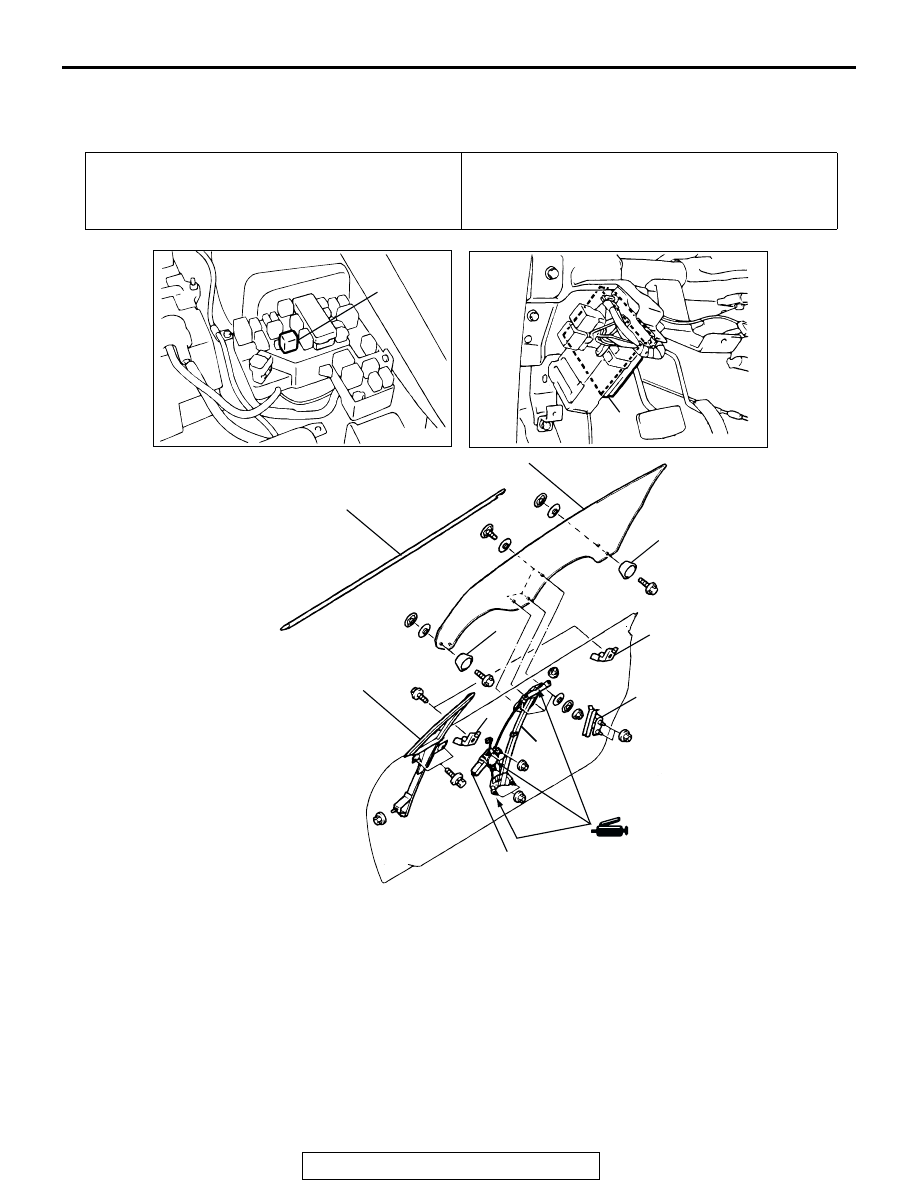
P.42-47

.)

AC101944 AB

1

3

2

4

5

6

5

6

7

8

9

10

REMOVAL STEPS
1. POWER WINDOW RELAY
2. ETACS-ECU
DOOR WINDOW GLASS AND DOOR 
WINDOW REGULATOR ASSEMBLY 
REMOVAL STEPS
3. DOOR DELTASASH
4. DOOR BELTLINE MOLDING 

(REFER TO 

P.42-66

.)

5. DOOR WINDOW GLASS UP STOP
6. DOOR WINDOW STOP

>>B<< 7. DOOR WINDOW GLASS

>>A<<

8. POWER WINDOW REGULATOR 

ASSEMBLY

>>A<<

9. POWER WINDOW MOTOR
10. DOOR WINDOW REAR LOWER 

SASH

DOOR

TSB Revision

BODY

42-58

INSTALLATION SERVICE POINT

.

>>A<< POWER WINDOW MOTOR/WINDOW REGULATOR 
ASSEMBLY INSTALLATION
1. Power window motor and window regulator assembly 

installation procedure

CAUTION

Do not operate the power window motor until the glass 
installation is finished.

(1) Connect the power window motor to the body-side 

harness connector, and then turn on the ignition switch.

(2) Continue to pull the power window switch until the power 

window motor stops.
NOTE: Power window motor stops automatically and the 
limit switch incorporated in the power motor will be reset.

(3) Turn off the ignition switch, and then remove window 

motor from the body-side harness connector. 

(4) Align the power window motor drive shaft and the square 

hole in the drum by the following procedure, while using 
the guide and the opening in the motor housing as a 
reference for the installation position.

a. Align the square hole with the drive shaft by sliding the 

glass bracket (glass mounting section) or by turning 
the drum using a ratchet wrench [with a socket 
diameter of 12.7 mm (0.50 inches)].

b. Turn the drum to position the glass bracket as shown 

in the illustration. Support the drum and the guide with 
your hand while turning the drum, otherwise the wires 
may pull out of the drum.

c. If the wires pull out of the drum, re-insert them by 

following the drum and regulator wire installation 
procedure.

AC000485

DRUM

GUIDE

SQUARE

HOLE

GUIDE

DRIVESHAFT

AB

AC000486

GLASS BRACKET

RATCHET WRENCH

AB

AC000487

GLASS

BRACKET

APPROXIMATELY

85 mm (3.3 in)

AB

DOOR

TSB Revision

BODY

42-59

(5) Align the guide and the opening of the motor housing, 

and slide the guide into the motor housing while holding 
the guide and drum.

CAUTION

Make sure that the metal cover is installed securely and 
does not move, in order to stop the drum from vibrating. If 
the drum vibrates, the glass may not slide up and down 
smoothly, or it may fall down.

(6) install the metal cover securely to housing.

2. Drum and regulator wire installation procedure

(1) Place the drum, guide and regulator on a work bench as 

shown in the illustration.
a. Place the drum so that the square hole is facing 

upward.

b. Place the guide so that the slits are facing upward.
c. Place the regulator so that the glass bracket is facing 

downward. Position the glass bracket so that glass is 
in the fully-open position.

(2) Pass the springs over the wires, and then install the 

lowering wire to the guide first, followed by the lifting wire. 
(The lifting wire should be on top of the lowering wire.)

AC000488AB

AC000489

MOUNTING

SCREW

METAL COVER

AB

AC000490

GUIDE

DRUM

SQUARE HOLE

SLIT

SPRING A

LIFTING

WIRE

LOWERING
WIRE

SPRING B

AB

AC000491

LOWERING

WIRE

LIFTING

WIRE

GUIDE

SLIT

SPRING

AB

DOOR

TSB Revision

BODY

42-60

(3) Use some narrow-gauge wire [approximately 0.5 mm 

(0.02 inches) diameter] to compress the springs, and 
then tie the narrow-gauge wire a to the slits in the guide.

(4) Insert the end of the lowering wire into the wire hole at 

the bottom of the drum, and then wrap the bottom so that 
there is no slackness in the wire.

(5) Install the lifting wire to the drum as following:

a. Insert the end of the lifting wire into the wire hole at the 

top of the drum.

b. Raise the front of the drum until the drum is vertical, 

and then position the lifting wire in the groove of the 
drum.

AC000492

NARROW-

GAUGE

WIRE

AB

AC000493

SLIT

AB

AC000494

LOWERING WIRE

AB

AC000495

LIFTING WIRE

AB

AC000496AB


Content   ..  956  957  958  959   ..