Mitsubishi Eclipse. Manual - part 863


  Index      Mitsubishi     Mitsubishi Eclipse - service repair manual 2004 year


Search            


Content   ..  861  862  863  864   ..


Mitsubishi Eclipse. Manual - part 863


ROCKER ARMS AND CAMSHAFT

TSB Revision

ENGINE OVERHAUL <2.4L>

11B-29

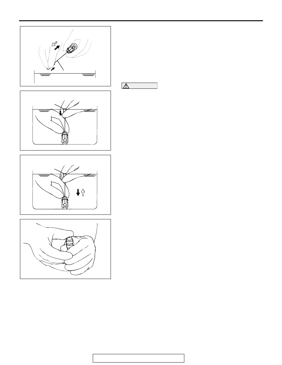
6. Remove the lash adjuster from the container. Then, push 

down the steel ball gently and push the plunger to eliminate 
diesel fuel from the pressure chamber.

CAUTION

Do not use container C for cleaning. If cleaning is per-
formed in container C, foreign matter could enter the pres-
sure chamber when the chamber is filled with diesel fuel.
7. Place the lash adjuster in container C. Then, gently push 

down the internal steel ball using wire [0.5 mm (0.020 inch) 
in diameter] or special tool MD998442.

8. Stand the lash adjuster with its plunger at the top, then push 

the plunger downward firmly until it moves through its 
greatest possible stroke. Return the plunger slowly, then 
release the steel ball and allow the pressure chamber to fill 
with diesel fuel.

9. Remove the lash adjuster from the container, then stand the 

lash adjuster with its plunger at the top. Push the plunger 
firmly and check that it does not move. Also, check that the 
lash adjuster's height matches that of a new lash adjuster.
NOTE: If the lash adjuster contracts or moves, perform the 
operations (7) through (9) again to fill it with diesel fuel com-
pletely. Replace the lash adjuster if it still contracts or moves 
after performing these steps.

10.Stand the lash adjuster upright to prevent diesel fuel from 

spilling out. Do not allow the lash adjuster to become 
contaminated by dirt or other foreign matter. Fit the lash 
adjuster onto the engine as soon as possible.

AKX00507

WIRE OR MD998442

DIESEL FUEL

AB

AKX00508

DIESEL 
FUEL

WIRE OR MD998442

AB

AKX00509

DIESEL
FUEL

WIRE OR MD998442

AB

AKX00505

CYLINDER HEAD AND VALVES

TSB Revision

ENGINE OVERHAUL <2.4L>

11B-30

CYLINDER HEAD AND VALVES

REMOVAL AND INSTALLATION

M1113006900475

Required Special Tools:

• MB991654: Cylinder Head Bolt Wrench (12)

• MD998772: Valve Spring Compressor

• MD998774: Valve Stem Seal Installer

AK301714

78 ± 2 Nm
58 ± 1 ft-lb

20 ± 2 Nm
14 ± 1 ft-lb

 0 Nm

 0 in-lb

→ + 90˚ → + 90˚

APPLY ENGINE OIL
TO ALL MOVING
PARTS BEFORE
INSTALLATION.

2

4

5

6

13

16

18

7

3

11

19

9

8

10

15

20

AB

12

17

14

N

N

N

N

N

N

N

1

REMOVAL STEPS

<<A>> >>D<<

1. CYLINDER HEAD BOLT
2. CYLINDER HEAD ASSEMBLY

>>D<<

3. CYLINDER HEAD GASKET

<<B>> >>C<<

4. RETAINER LOCK
5. VALVE SPRING RETAINER

>>B<<

6. VALVE SPRING
7. INTAKE VALVE

<<B>> >>C<<

8. RETAINER LOCK
9. VALVE SPRING RETAINER

>>B<<

10.VALVE SPRING

11.EXHAUST VALVE

>>A<<

12.VALVE STEM SEAL
13.VALVE SPRING SEAT

>>A<<

14.VALVE STEM SEAL
15.VALVE SPRING SEAT
16.INTAKE VALVE GUIDE
17.EXHAUST VALVE GUIDE
18.INTAKE VALVE SEAT
19.EXHAUST VALVE SEAT
20.CYLINDER HEAD

REMOVAL STEPS (Continued)

CYLINDER HEAD AND VALVES

TSB Revision

ENGINE OVERHAUL <2.4L>

11B-31

REMOVAL SERVICE POINTS

.

<<A>> CYLINDER HEAD BOLTS REMOVAL
Using special tool MB991654, loosen the cylinder head bolts. 
Loosen each bolt evenly, little by little, by two or three steps.

.

<<B>> RETAINER LOCK REMOVAL
1. Set special tool MD998772 as illustrated to compress the 

valve spring. Remove the retainer lock.

2. Relieve the spring tension and remove the valve, retainer, 

spring, etc. Store removed valves, springs, and other parts, 
tagged to indicated their cylinder number and location for 
assembly.

INSTALLATION SERVICE POINTS

.

>>A<< VALVE STEM SEAL INSTALLATION

CAUTION

The special tool must be used to install the valve stem 
seal. Improper installation could result in oil leaking past 
the valve guide.
1. Install the valve spring seat.
2. Using special tool MD998774, install a new valve stem seal.

.

AKX00519

MB991654

AB

AKX00520

MD998772

AB

AKX00521

MD998774

AB

CYLINDER HEAD AND VALVES

TSB Revision

ENGINE OVERHAUL <2.4L>

11B-32

>>B<< VALVE SPRING INSTALLATION
Install the valve spring with its identification color painted end 
(larger pitch side) upward (toward the valve spring retainer).

.

>>C<< RETAINER LOCK INSTALLATION

CAUTION

Do not compress the valve spring excessively. It can dam-
age the stem seal.
1. Set special tool MD998772 as illustrated to compress the 

valve spring. Install the retainer locks.

2. Relieve the spring tension. Check that the retainer locks are 

seated correctly.

.

>>D<< CYLINDER HEAD BOLT INSTALLATION
1. When the removed cylinder head bolts are to be reused, 

check that the shank length of each bolt meets the limit. If it 
exceeds the limit, replace the bolts.

Limit: 99.4 mm (3.91 inches)

2. Apply engine oil to the thread of the bolts and to the 

washers.

3. Using special tool MB991654 tighten the bolts to the 

specified torque 78 N

⋅m (58 ft-lb), using the tightening 

sequence shown.

4. Loosen all bolts fully in the reverse order of tightening.
5. Retighten the loosened bolts to 20 N

⋅m (14 ft-lb) in the 

tightening sequence shown.

AKX00454

SPRING
RETAINER

IDENTIFICATION
COLOR

STEM
SEAL

SPRING
SEAT

AB

AKX00520

MD998772

AB

AKX00467

SHANK LENGTH

AB

AKX00526

TIMING BELT SIDE

8


6


1


3


9

10

4

2

 5

7

AB


Content   ..  861  862  863  864   ..