Mitsubishi Eclipse. Manual - part 864


  Index      Mitsubishi     Mitsubishi Eclipse - service repair manual 2004 year


Search            


Content   ..  862  863  864  865   ..


Mitsubishi Eclipse. Manual - part 864


CYLINDER HEAD AND VALVES

TSB Revision

ENGINE OVERHAUL <2.4L>

11B-33

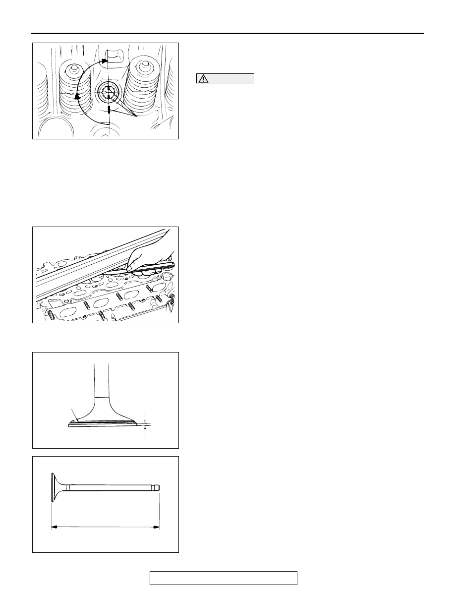
6. Make a paint mark across each bolt head and cylinder head.
7. Tighten the cylinder head bolts 90 degree angle in the 

specified order.

CAUTION

• If the bolt is turned less than 90 degree angle, proper 

fastening performance may not be achieved. Be careful 
to turn each bolt exactly 90 degree angle.

• If the bolt is overtightened, loosen the bolt completely 

and then retighten it by repeating the tightening proce-
dure from step 1.

8. Tighten the bolts another 90 degree angle in the same order 

as in step 7, and check that the paint marks on the cylinder 
head bolt are aligned with the paint marks on the cylinder 
head.

INSPECTION

M1113007000055

.

CYLINDER HEAD
1. Check the cylinder head gasket surface for flatness by using 

a straight edge and feeler gauge.

Standard value: 0.05 mm (0.002 inch)
Limit: 0.2 mm (0.007 inch)

2. If it exceeds the limit, correct to meet specification.

Grinding limit: *0.2 mm (0.007 inch)
* Includes combined with cylinder block grinding.
Cylinder head height (Specification when new):
120 mm (4.7 inches)

.

VALVE
1. Check the valve seat contact. Valve seat contact should be 

uniform at the center of the valve face. If incorrect, reface 
using a valve refacer.

2. If the margin is below the limit, replace the valve.

Standard value:

<Intake> 1.0 mm (0.03 inch)
<Exhaust> 1.2 mm (0.04 inch)

Minimum limit:

<Intake> 0.5 mm (0.02 inch)
<Exhaust> 0.7 mm (0.03 inch)

3. Measure the valve's total length. If the measurement is less 

than the limit, replace the valve.

Standard value:

<Intake> 112.30 mm (4.421 inches)
<Exhaust> 114.11 mm (4.493 inches)

Minimum limit:

<Intake> 111.80 mm (4.402 inches)
<Exhaust> 113.61 mm (4.473 inches)

AKX00449

PAINT MARK

AB

90˚

90˚

AKX00604

AKX00455

VALVE SEAT
CONTACT

MARGIN

AB

AKX00502

CYLINDER HEAD AND VALVES

TSB Revision

ENGINE OVERHAUL <2.4L>

11B-34

.

VALVE SPRING
1. Measure the free height of the spring. If it is less than the 

limit, replace.

Standard value: 51.0 mm (2.00 inches)
Minimum limit: 50.0 mm (1.97 inches)

2. Measure the squareness of the spring. If it exceeds the limit, 

replace.

Standard value: 2 degree angle or less
Limit: 4 degree angle

.

VALVE GUIDE
Measure the clearance between the valve guide and valve 
stem. If it exceeds the limit, replace the valve guide or valve, or 
both.

Standard value:

<Intake> 0.02 

 0.05 mm (0.0008  0.0019 inch)

<Exhaust> 0.03 

 0.07 mm (0.0012  0.0027 inch)

Limit:

<Intake> 0.10 mm (0.003 inch)
<Exhaust> 0.15 mm (0.005 inch)

.

VALVE SEAT
Assemble the valve, then measure the valve stem projection 
between the end of the valve stem and the spring seating sur-
face. If the measurement exceeds the specified limit, replace 
the valve seat.

Standard value: 49.30 mm (1.941 inches)
Limit: 49.80 mm (1.960 inches)

VALVE SEAT RECONDITIONING PROCEDURE

1. Before correcting the valve seat, check for clearance 

between the valve guide and valve and, if necessary, 
replace the valve guide.

2. Using the seat grinder, correct to obtain the specified seat 

width and angle.

3. After correcting the valve seat, lap the valve and valve seat 

using lapping compound. Then, check the valve stem 
projection.

AKX00441

OUT OF 
SQUARE

FREE
HEIGHT

AB

AKX00565

VALVE
GUIDE

GUIDE INSIDE DIAMETER

STEM OUTSIDE DIAMETER

AB

AKX00536

VALVE STEM END

VALVE STEM
PROJECTION

SPRING SEATING
SURFACE

AB

AKX00569

43.5˚ – 44˚

0.9 – 1.3 mm 
(0.04 – 0.05 in)

65˚

30˚

AB

CYLINDER HEAD AND VALVES

TSB Revision

ENGINE OVERHAUL <2.4L>

11B-35

VALVE SEAT REPLACEMENT PROCEDURE

1. Cut the valve seat from the inside to thin the wall thickness. 

Then, remove the valve seat.

2. Rebore the valve seat hole in the cylinder head to a selected 

oversize valve seat diameter.

Intake seat ring hole diameters

0.3 oversize 

34.30 

 34.33 mm (1.3504  1.3515 inches)

0.6 oversize 

34.60 

 34.63 mm (1.3622  1.3633 inches)

Exhaust seat ring hole diameters

0.3 oversize 

31.80 

 31.83 mm (1.2520  1.2531 inches)

0.6 oversize 

32.10 

 32.13 mm (1.2638  1.2649 inches)

3. Before fitting the valve seat, either heat the cylinder head up 

to approximately 250

°C (482°F) or cool the valve seat in 

liquid nitrogen, to prevent the cylinder head bore from 
galling.

4. Using a valve seat cutter, correct the valve seat to the 

specified width and angle. 
See "VALVE SEAT RECONDITIONING PROCEDURE" on 
the previous page.

VALVE GUIDE REPLACEMENT PROCEDURE

1. Using a press, remove the valve guide toward the cylinder 

block.

CAUTION

Do not install a valve guide of the same size again.
2. Rebore the valve guide hole of the cylinder head so that it 

fits the press-fitted oversize valve guide.

Valve guide hole diameters

0.05 oversize 11.05 

 11.07 mm (0.4350  0.4358 inch)

0.25 oversize 11.25 

 11.27 mm (0.4430  0.4436 inch)

0.50 oversize 11.50 

 11.52 mm (0.4528  0.4535 inch)

AKX00444

0.5 – 1.0 mm (0.02 – 0.03 in)

CUT AWAY

0.5 – 1.0 mm 
(0.02 – 0.03 in)

AB

AKX00445

HEIGHT OF 
SEAT RING

OVERSIZE DIAMETER

AB

AKX00571

REMOVAL

INSTALLATION

PRESS

PRESS

PUSHROD

PUSHROD

VALVE
GUIDE

VALVE
GUIDE

AB

FRONT CASE AND OIL PUMP

TSB Revision

ENGINE OVERHAUL <2.4L>

11B-36

3. Press-fit the valve guide until it protrudes 14.0 mm (0.55 

inch) from the cylinder head top surface as shown in the 
illustration.
NOTE: When press-fitting the valve guide, work from the 
cylinder head top surface.
NOTE: Pay attention to the difference in length of the valve 
guides. [Intake side: 45.5 mm (1.79 inches); exhaust side: 
50.5 mm (1.99 inches)]
NOTE: After installing the valve guides, insert new valves in 
them to check for smooth operation. 

FRONT CASE AND OIL PUMP

REMOVAL AND INSTALLATION

M1113007200093

AKX00597

14mm
(0.55 in)

AB

AKX00495

APPLY ENGINE OIL
TO ALL MOVING
PARTS BEFORE
INSTALLATION.

19 ± 3 N·m
14 ± 2 ft-lb

24 ± 3 N·m
17 ± 2 ft-lb

9.8 ± 2 N·m
87 ± 17 in-lb

19 ± 3 N·m
14 ± 2 ft-lb

17 ± 1 N·m 
12 ± 1 ft-lb

24 ± 3 N·m 
17 ± 2 ft-lb

39 ± 5 N·m 
29 ± 4 ft-lb

36 ± 3 N·m 
27 ± 2 ft-lb 19 ± 3 N·m

14 ± 2 ft-lb

6.9 ± 1 N·m
61 ± 9 in-lb

44 ± 5 N·m 
33 ± 4 ft-lb

30

28

2

27

18

17

29

25

26

19

24

20

21

16

15

22

23

14

8

9

13

10

3

7

4

6

11

1

N

N

N

N

N

N

N

N

N

N

N

AB

12

5


Content   ..  862  863  864  865   ..