Mitsubishi Eclipse. Manual - part 854
TRANSAXLE ASSEMBLY
TSB Revision
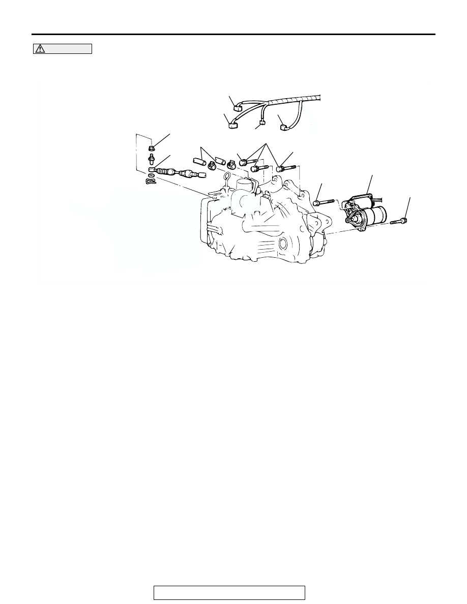
AUTOMATIC TRANSAXLE
23A-425
CAUTION
*
: Indicates parts which should be partially tightened, and then fully tightened after placing the vehicle
on the ground and loading the full weight of the engine on the vehicle body.
AC001639AG
30 ± 3 N·m
23 ± 2 ft-lb
7
12 ± 2 N·m
102 ± 22 in-lb
88 ± 10 N·m
65 ± 7 ft-lb
2
1
8
6
5
4
3
<3.0L ENGINE>
30 ± 3 N·m
23 ± 2 ft-lb
73 ± 10 N·m
54 ± 7 ft-lb
REMOVAL STEPS
1.
TRANSAXLE CONTROL CABLE
CONNECTION
2.
TRANSAXLE OIL COOLER
HOSES CONNECTION
3.
TRANSMISSION RANGE
SWITCH CONNECTOR
4.
A/T CONTROL SOLENOID
VALVE ASSEMBLY
CONNECTOR
5.
INPUT SHAFT SPEED SENSOR
CONNECTOR
6.
OUTPUT SHAFT SPEED
SENSOR CONNECTOR
<<A>>
7.
STARTER MOTOR
8.
TRANSAXLE UPPER
CONNECTING BOLTS
REMOVAL STEPS (Continued)