Mitsubishi Eclipse. Manual - part 853
A/T KEY INTERLOCK AND SHIFT LOCK MECHANISMS
TSB Revision
AUTOMATIC TRANSAXLE
23A-421
A/T KEY INTERLOCK AND SHIFT LOCK MECHANISMS
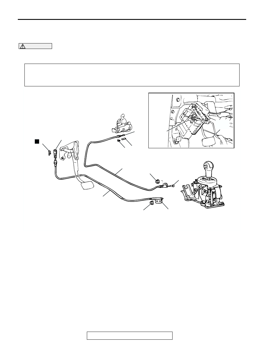
REMOVAL AND INSTALLATION
M1232001200411
CAUTION
When removing and installing the key interlock cable and shift lock cable, be careful not to hit the
SRS-ECU.
Pre-removal and Post-installation Operation
• Floor Console Removal and Installation (Refer to GROUP 52A
.)
• Key Interlock Mechanism Check (Refer to
.) <Post-installation>
• Shift Lock Mechanism Check (Refer to
.) <Post-installation>
AC001636AB
12 ± 2 N·m
102 ± 22 in-lb
7
N
6
9
BRAKE
PEDAL
1
10
12 ± 2 N·m
102 ± 22 in-lb
5
4
3
2
8
KEY INTERLOCK CABLE
REMOVAL STEPS
>>C<<
1.
KEY INTERLOCK CABLE
CONNECTION (SELECTOR
LEVER SIDE)
•
LOWER COLUMN COVER
(REFER TO GROUP 37A,
STEERING WHEEL AND SHAFT
2.
COVER
>>B<<
3.
KEY INTERLOCK CABLE
CONNECTION (STEERING
LOCK CYLINDER SIDE)
4.
SLIDER
5.
KEY INTERLOCK CABLE
SHIFT LOCK CABLE REMOVAL
STEPS
>>A<<
6.
SHIFT LOCK CABLE
CONNECTION (SELECTOR
LEVER SIDE)
7.
COTTER PIN
8.
SHIFT LOCK CABLE
CONNECTION (BRAKE PEDAL
SIDE)
9.
SHIFT LOCK CABLE
ETACS-ECU REMOVAL
10. ETACS-ECU