Mitsubishi Eclipse. Manual - part 851


  Index      Mitsubishi     Mitsubishi Eclipse - service repair manual 2004 year


Search            


Content   ..  849  850  851  852   ..


Mitsubishi Eclipse. Manual - part 851


ON-VEHICLE SERVICE

TSB Revision

AUTOMATIC TRANSAXLE

23A-413

KEY INTERLOCK MECHANISM CHECK

M1232000900291

1. Perform the following inspection.

2. When any of the above checks are not normal, adjust the 

key interlock cable by following procedure.

(1) Remove the floor console. (Refer to GROUP 52A 

− Floor 

Console Assembly 

P.52A-7

.)

(2) Shift the selector lever to "P" position.
(3) Turn the ignition key to the "LOCK" (OFF) position.
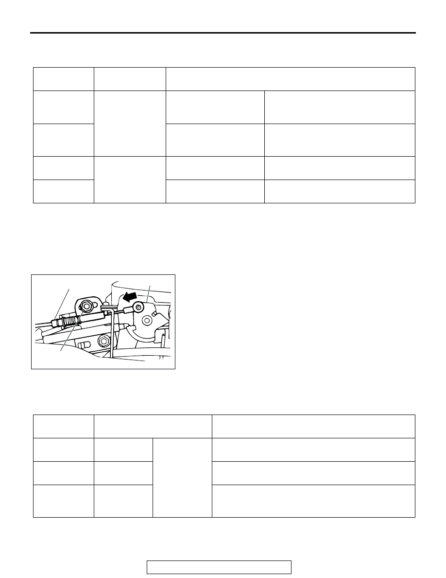
(4) Loosen the locking nut of the key interlock cable.
(5) Push the cable joint on the lock cam gently toward the 

arrow until the cable stops. Tighten the locking nut.

Tightening torque: 12 

± 2 Nm (102 ± 22 in-lb)

(6) Install the floor console. (Refer to GROUP 52A 

− Floor 

Console Assembly 

P.52A-7

.)

3. After adjusting, check the operation once more. If the 

operation is still incorrect, replace the key interlock cable. 
(Refer to 

P.23A-421

.)

SHIFT LOCK MECHANISM CHECK

M1232001000280

1. Perform the following inspections.

2. When any of the above shift lock inspection procedures fail, 

adjust the shift lock cable as follows:

INSPECTION 
PROCEDURE

INSPECTION 
REQUIREMENTS

KEY INTERLOCK 
(NORMAL OPERATION)

1

Brake pedal: 
Depressed

Ignition key position: 
"LOCK" (OFF) or removed

Unable to push in the selector lever push 
button and move the lever out of the "P" 
position.

2

Ignition key position: 
"ACC"

Able to push in the selector lever push 
button, move the lever out of the "P" 
position, and shift to any position. 

3

Brake pedal: Not 
depressed

Selector lever: Other than 
"P" position

Unable to turn the ignition key to the 
"LOCK" (OFF) position.

4

Selector lever: "P" position Able to turn the ignition key to the 

"LOCK" (OFF) position.

AC0001627AB

LOCKING
NUT

KEY INTERLOCK CABLE

LOCK CAM

INSPECTION 
PROCEDURE

INSPECTION 
REQUIREMENTS

CHECK DETAILS (NORMAL OPERATION)

1

Brake pedal: 
Not depressed

Ignition key 
position: "ACC"

When the selector lever push button is depressed, the 
selector lever can not be shifted out of the "P" position.

2

Brake pedal: 
Depressed

When the selector lever push button is depressed, the 
selector lever can be shifted smoothly to other positions.

3

Brake pedal: 
Not depressed

When the selector lever push button is depressed, the 
selector lever can be shifted smoothly from the "R" 
position to the "P position.

ON-VEHICLE SERVICE

TSB Revision

AUTOMATIC TRANSAXLE

23A-414

(1) Remove the floor console. (Refer to GROUP 52A 

− Floor 

Console Assembly 

P.52A-7

.)

(2) Shift the selector lever to the "P" position.
(3) Loosen the locking nut of the shift lock cable.
(4) Adjust the cable so that the end of the shift lock cable is 

above the red line on the lock cam and tighten the locking 
nut.

Tightening torque: 12 

± 2 Nm (102 ± 22 in-lb)

(5) After adjusting, retest the shift lock cable operation. 

Replace the shift lock cable if it does not operate 
properly. (Refer to 

P.23A-421

.)

(6) Install the floor console. (Refer to GROUP 52A 

− Floor 

Console Assembly 

P.52A-7

.)

AC001628AB

RED MARK

LOCKING
NUT

LOCK CAM

SHIFT LOCK CABLE

TRANSAXLE CONTROL

TSB Revision

AUTOMATIC TRANSAXLE

23A-415

TRANSAXLE CONTROL

REMOVAL AND INSTALLATION

M1231006600336

CAUTION

When removing and installing the transaxle control cable, be careful not to hit the SRS-ECU.

Pre-removal and Post-installation Operation
• Air Cleaner Assembly Removal and Installation (Refer to GROUP 15 

P.15-6

.)

• Battery and Battery Tray Removal and Installation (Refer to GROUP 54A 

P.54A-8

.)

• Instrument Panel Under Cover Removal and Installation (Refer to GROUP 52A − Instrument Panel Assembly 

P.52A-2

.)

• Floor Console Assembly Removal and Installation (Refer to GROUP 52A 

P.52A-7

.)

• Selector Lever Operation Check (Refer to 

P.23A-412

.) <Post-installation>

• Key Interlock Mechanism Check (Refer to 

P.23A-413

.) <Post-installation>

• Shift Lock Mechanism Check (Refer to 

P.23A-413

.) <Post-installation>

AC001630AB

1

2

4

5

12 ± 2 N·m
102 ± 22 in-lb 

3

10

12 ± 2 N·m
102 ± 22 in-lb

8

12 ± 2 N·m
102 ± 22 in-lb

7

6

<VEHICLES WITHOUT SPORT MODE>

12 ± 2 N·m
102 ± 22 in-lb

AC001631AB

1

2

4

5

12 ± 2 N·m
102 ± 22 in-lb

3

10

12 ±  2 N·m
102 ± 22 in-lb 

9

12 ± 2 N·m
102 ± 22 in-lb

7

6

<VEHICLES WITH SPORT MODE>

12 ± 2 N·m
102 ± 22 in-lb

TRANSAXLE CONTROL

TSB Revision

AUTOMATIC TRANSAXLE

23A-416

INSTALLATION SERVICE POINTS

.

>>A<< SHIFT LOCK CABLE (SELECTOR LEVER SIDE) 
INSTALLATION
1. Shift the selector lever to the "P" position.
2. Fasten the shift lock cable at the position where the end of 

the shift lock cable is above the red line on the lock cam.

.

>>B<< KEY INTERLOCK CABLE (SELECTOR LEVER SIDE) 
INSTALLATION
1. Shift the selector lever to the "P" position.
2. Turn the ignition key to the "LOCK" (OFF) position.
3. Slide the washer and spring toward the lock cam, insert the 

cable into the stand off bracket and release the spring.

4.  Lightly push the key interlock cable into the key interlock 

cable housing toward the arrow (A) direction until the cable 
movement stops and the cable end eye is aligned with the 
shaft on the lock cam. Tighten the lock nut. Snap the cable 
end eye onto the shaft of the lock cam.

Tightening torque: 12 

± 2 Nm (102 ± 22 in-lb)

.

>>C<< NUT INSTALLATION
1. Place the transaxle manual control lever in the "N" position.
2. Place the selector lever in the "N" position.

TRANSAXLE CONTROL 
CABLE ASSEMBLY REMOVAL 
STEPS

>>C<<

1.

NUT

2.

ADJUSTER

3.

TRANSAXLE CONTROL CABLE 
ASSEMBLY CONNECTION 
(SELECTOR LEVER ASSEMBLY 
SIDE)

4.

TRANSAXLE CONTROL CABLE 
ASSEMBLY (TRANSAXLE SIDE)

HEATER/COOLER UNIT 
(REFER TO GROUP 55, 
HEATER/COOLER UNIT, 
HEATER CORE AND 
EVAPORATOR 

P.55-34

.)

5.

TRANSAXLE CONTROL CABLE 
ASSEMBLY

SELECTOR LEVER ASSEMBLY 
REMOVAL STEPS

3.

TRANSAXLE CONTROL CABLE 
ASSEMBLY CONNECTION 
(SELECTOR LEVER ASSEMBLY 
SIDE)

>>B<<

6.

KEY INTERLOCK CABLE 
CONNECTION (SELECTOR 
LEVER SIDE)

>>A<<

7.

SHIFT LACK CABLE 
CONNECTION (SELECTOR 
LEVER SIDE)

8.

A/T SELECTOR LEVER 
POSITION ILLUMINATION 
LIGHT CONNECTOR

9.

HARNESS CONNECTOR

10. SELECTOR LEVER ASSEMBLY

AC001628AC

RED MARK

SHIFT LOCK CABLE

LOCK CAM

AC0001627AC

SPRING

WASHER

LOCKING NUT

LOCK CAM

KEY INTERLOCK CABLE

A


Content   ..  849  850  851  852   ..