Mitsubishi Colt Ralliart. Manual - part 647
ON-VEHICLE SERVICE
ENGINE MECHANICAL <4G1>
11C-8
ON-VEHICLE SERVICE
DRIVE BELT TENSION CHECK AND
ADJUSTMENT
M1111003101400
ALTERNATOR DRIVE BELT TENSION
CHECK
Check the drive belt tension in the following proce-
dure.
Standard value:
Item
When
checked
When
adjusted
When
replaced
Vibration
frequency
Hz
218
− 266
231
− 255 308 − 344
Tension N
392
− 588
441
− 539 785 − 981
Deflection
mm
(Reference)
6.3
− 8.0
6.6
− 7.5
4.1
− 5.0
<When the vibration frequency is
measured {Special tool (MB992080) is
used}: Recommendation>
NOTE: The vibration frequency measuring method is
recommended for check and adjustment of the drive
belt tension.
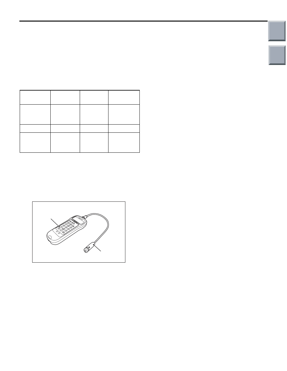
AC507219AB
MB992082
MB992081
Belt tension meter set (MB992080)
1. Connect the Special tool microphone assembly
(MB992082) to the Special tool belt tension meter
(MB992081) of the Special tool belt tension meter
set (MB992080).
2. Press the "POWER" button to turn on the power
supply.
3. Press number key 1. Check to ensure that "No.
01" appears on the upper left of the display and
that the following numeric values are displayed for
individual items (M, W, and S):
M 000.9 g/m
W 010.0 mm/R
S 0100 mm
If numeric values have not been entered (new
tool), set them according to the belt specifications
as shown below. Once you set them, you do not
have to set them again. The settings remain
undeleted even after battery replacement.
NOTE: This operation is to temporarily set the
preset data such as the belt specifications,
because if the measurement is taken without input
of the belt specifications, conversion to tension
value (N) cannot be made, resulting in judgement
of error.
<Setting procedure>
(1) Press down the "MASS" button till the belt
mass select display appears.
(2) Press the "UP" or "DOWN" button to select "01
1.5GT 0.9" and press the "MEASURE" button
to decide it.
Check to ensure that "M 000.9 g/m" is
displayed.
(3) Press the "WIDTH" button to change to the
belt width input display.
(4) Press number keys 0, 1, 0, and 0 sequentially,
and press the "SELECT" button to apply them.
Check to ensure that "W 010.0 mm/R"
appears on the display.
(5) Press the "SPAN" button to change to the
span length input display.
(6) Press number keys 0, 1, 0, and 0 sequentially,
and press the "SELECT" button to apply them.
Check to ensure that "S 0100 mm" appears on
the display.
4. Press "Hz" button twice to change the display to
the frequency display (Hz).
Main
Index
Group
TOC