Mitsubishi Colt Ralliart. Manual - part 648


  Index      Mitsubishi     Mitsubishi Colt Ralliart - service repair manual


Search            


Content   ..  646  647  648  649   ..


Mitsubishi Colt Ralliart. Manual - part 648


ON-VEHICLE SERVICE

ENGINE MECHANICAL <4G1>

11C-12

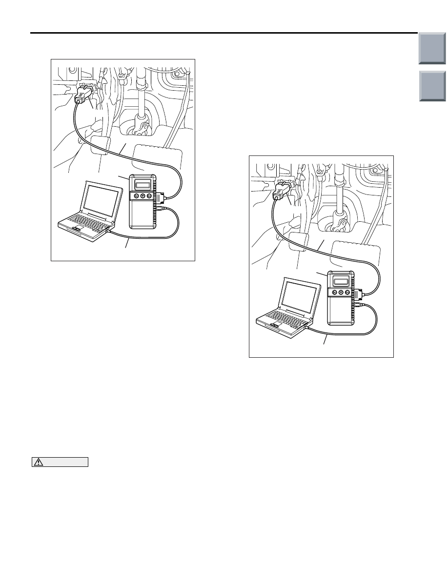
IGNITION TIMING CHECK

M1111001701235

AK203215

MB991910

16-PIN

MB991827

MB991824 

AC

1. Before inspection, set the vehicle to the 

pre-inspection condition.

2. Turn the ignition switch to the "LOCK" (OFF) 

position and then connect the M.U.T.-III to the 
diagnosis connector.

3. Set the timing light to the power supply line 

(terminal No.1) of the ignition coil No.1.

4. Start the engine and let it run at idle.
5. Use the M.U.T.-III to measure engine idle speed 

and check that it is approximately 750 r/min.

6. Select No. 17 of the M.U.T.-III Actuator test.
7. Check that basic ignition timing is within the 

standard value.

Standard value: 5

° BTDC ± 3°

8. If the basic ignition timing is outside the standard 

value, inspect the MPI system (Refer to GROUP 
13B 

− Troubleshooting − Inspection chart for 

diagnosis code 

P.13B-18

).

CAUTION

If the test is not cancelled, a forced driving will 
continue for 27 minutes. Driving under this con-
dition may damage the engine.
9. Press the M.U.T.-III clear key (Select a forced 

driving cancel mode) to release the Actuator test.

10.Check that ignition timing is at the standard value.

Standard value: approximately 10

° BTDC

NOTE: 

.

The ignition timing may fluctuate within 

±

 7

°


BTDC. This is normal.

In higher altitude, the ignition timing is more 
advanced than the standard value by approxi-
mately 5

°

.

11.Remove the timing light.
12.Turn off the ignition switch and then remove the 

M.U.T.-III.

IDLE SPEED CHECK

M1111003501130

AK203215

MB991910

16-PIN

MB991827

MB991824 

AC

1. Before inspection, set the vehicle to the 

pre-inspection condition.

2. Turn the ignition switch to "LOCK" (OFF) position.
3. Connect the M.U.T.-III to the diagnosis connector.
4. Set the timing light to the power supply line 

(terminal No.1) of the ignition coil No.1.

5. Start the engine and let it run at idle.
6. Check that ignition timing is at the standard value.

Standard value: approximately 10

° BTDC

7. Check the idle speed.

Standard value: 750 

± 50 r/min 

NOTE: 

.

The idle speed is controlled automatically by 
the idle speed control system.

When using the M.U.T.-III, select item No. 22 
and take a reading of the idle speed.

Main

Index

Group

TOC

ON-VEHICLE SERVICE

ENGINE MECHANICAL <4G1>

11C-13

8. If the idle speed is outside the standard value, 

inspect the MPI system (Refer to GROUP 13B 

− 

Troubleshooting 

− Inspection chart for diagnosis 

code 

P.13B-18

).

IDLE MIXTURE CHECK

M1111002100868

AK203215

MB991910

16-PIN

MB991827

MB991824 

AC

1. Before inspection, set the vehicle to the 

pre-inspection condition.

2. Turn the ignition switch to "LOCK" (OFF) position.
3. Connect the M.U.T.-III to the diagnosis connector.
4. Set the timing light to the power supply line 

(terminal No.1) of the ignition coil No.1.

5. Start the engine and let it run at idle.
6. Check that ignition timing is at the standard value.

Standard value: approximately 10

° BTDC

7. Run the engine at 2,500 r/min for 2 minutes.
8. Set the CO, HC tester.
9. Check the CO contents and the HC contents at 

idle.

Standard value

CO contents: 0.5% or less
HC contents: 100 ppm or less

10.If there is a deviation from the standard value, 

inspect the MPI system (Refer to GROUP 13B 

− 

Troubleshooting 

− Inspection chart diagnosis 

code 

P.13B-18

)

COMPRESSION PRESSURE CHECK

M1111002601297

AK402211

Crank angle sensor
connector

AC

1. Before inspection, set the vehicle to the 

pre-inspection condition.

2. Remove all of the ignition coil and spark plugs.
3. Disconnect the crank angle sensor connector.

NOTE: Doing this will prevent the 
engine-CVT-ECU from carrying out ignition and 
fuel injection.

CAUTION

• Keep away from the spark plug hole when 

cranking.

• If compression is measured with water, oil, 

fuel, etc., that has come from cracks inside 
the cylinder, these materials will become 
heated and will gush out from the spark plug 
hole, which is dangerous.

4. Cover the spark plug hole with a shop towel etc., 

and after the engine has been cranked, check that 
no foreign material is adhering to the shop towel.

AK202358

Compression
gauge

AC

5. Set compression gauge to one of the spark plug 

holes.

6. Crank the engine with the throttle valve fully open 

and measure the compression pressure.

Standard value (at engine speed of 300 

r/min):

1,210 kPa

Limit (at engine speed of 300 r/min):

Minimum 830 kPa

Main

Index

Group

TOC

ON-VEHICLE SERVICE

ENGINE MECHANICAL <4G1>

11C-14

7. Measure the compression pressure for all the 

cylinders, and check that the pressure differences 
of the cylinders are below the limit.

Limit: Maximum 98 kPa

8. If there is a cylinder with compression or a 

compression difference that is outside the limit, 
pour a small amount of engine oil through the 
spark plug hole, and repeat the operations in 
steps from (5) to (7).
(1) If the compression increases after oil is added, 

the cause of the malfunction is a worn or 
damaged piston ring and/or cylinder inner 
surface.

(2) If the compression dose not rise after oil is 

added, the cause is a burnt or defective valve 
seat, or pressure is leaking from the gasket.

9. Connect the crank angle sensor connector.
10.Install the spark plugs and ignition coils.
11.Use the M.U.T.-III to erase the diagnosis codes.

NOTE: This will erase the diagnosis code result-
ing from the crank angle sensor connector being 
disconnected.

MANIFOLD VACUUM CHECK

M1111002700967

AK203215

MB991910

16-PIN

MB991827

MB991824 

AC

1. Before inspection, set the vehicle to the 

pre-inspection condition.

2. Turn the ignition switch to "LOCK" (OFF) position.
3. Connect a tachometer or connect the M.U.T.-III to 

the diagnosis connector.

AK402146AC

Vacuum gauge

4. Attach a three-way joint to the vacuum hose 

between the fuel pressure solenoid valve and the 
inlet manifold, and connect a vacuum gauge.

5. Start the engine and check that idle speed is 

approximately 750 r/min.

6. Check the inlet manifold vacuum.

Limit: Minimum 60 kPa

7. Turn off the ignition switch.
8. Remove the vacuum gauge and the three-way 

joint, and then connect the vacuum hose.

9. Remove the engine tachometer or the M.U.T.-III.

Main

Index

Group

TOC

ON-VEHICLE SERVICE

ENGINE MECHANICAL <4G1>

11C-15

LASH ADJUSTER CHECK

M1111002900637

If an abnormal noise (knocking) that seems to be 
coming from the lash adjuster is heard after starting 
the engine and dose not stop, carry out the following 
check.
NOTE: 

.

If the vehicle is parked on a slope fir a long period 
of time, the amount of oil inside the lash adjuster 
will decrease, and air may get into the high pres-
sure chamber when starting the engine.

After parking the vehicle for long periods, the oil 
drains out of the oil passage, and it takes time for 
the oil to be supplied to the lash adjuster, so air 
can get into the high-pressure chamber.

If either of the above situations occur, the abnor-
mal noise can be eliminated by bleeding the air 
from inside the lash adjusters.

The abnormal noise which is caused by a prob-
lem with the lash adjusters is generated after the 
engine is started, and will vary according to the 
engine speed. However, this noise is not related 
to the actual engine load.

Because of this, if the noise dose not occur immedi-

ately after the engine is started, if it dose not 
change in accordance with the engine speed, or if 
it changes in accordance with the engine load, 
the source of the noise is not the lash adjusters.

If there is a problem with the lash adjusters, the 
noise will almost never disappear, even if the 
engine has been run at idle to let it warm up.

The only case where the noise might disappear is if 

the oil in the engine has not been looked after 
properly and oil sludge has caused the lash 
adjusters to stick.

<FUNCTIONAL INSPECTION>

1. Start the engine.
2. Check that the noise occurs immediately after the 

engine is started, and that the noise changes in 
accordance with changes in the engine speed.
If the noise dose not occur immediately after the 
engine is started, or if it dose not change in 
accordance with the engine speed, the problem is 
not being caused by the lash adjusters, so check 
for some other cause of the problem. Moreover, if 
the noise dose not change in accordance with the 
engine speed, the cause of the problem is 
probably not with the engine (In these cases, the 
lash adjusters are normal).

3. While the engine is idling, check that the noise 

level does not change when the engine load is 
varied (for example, by shifting from N to D).
If the noise level changes, the cause of the noise 
is probably parts striking because of worn 
crankshaft bearings or connecting rod bearings 
(In such cases, the lash adjusters are normal).

4. After the engine has warmed up, run it at idle and 

check if any noise can be heard.
If the noise has become smaller or disappeared, 
oil sludge could make the lash adjusters stick. 
Clean the lash adjusters (Refer to GROUP 11D 

− 

Rocker Arms and Camshaft 

− Rocker Arms and 

Camshaft Inspection 

P.11D-30

). If not improved, 

go to step 5.

5. Bleed air from the lash adjusters (Refer to 

P.11C-16

).

6. If the noise has not disappeared even after the air 

bleeding, clean the lash adjusters (Refer to 
GROUP 11D 

− Rocker Arms and Camshaft − 

Rocker Arms and Camshaft Inspection 

P.11D-30

).

Main

Index

Group

TOC


Content   ..  646  647  648  649   ..