Mitsubishi Colt Ralliart. Manual - part 645
STEERING WHEEL SENSOR
ACTIVE STABILITY CONTROL SYSTEM (ASC)
35C-125
STEERING WHEEL SENSOR
REMOVAL AND INSTALLATION
M1357002800012
CAUTION
• When centring the clock spring, always remove the clock spring from the column switch in
advance. Otherwise, the sensor may be damaged.
• If the centre of the clock spring is not correctly aligned, the steering wheel may not be turned fully
or the cable inside the clock spring may be broken, causing the SRS air bag to be inoperative or
operated incorrectly.
• Before removing the steering wheel/air bag module assembly, refer to GROUP 52B − Service Pre-
cautions
and Air Bag Module Clock Spring
• When the steering wheel sensor is replaced, always carry out calibration to make ASC-ECU learn
the neutral point. (Refer to
Pre-removal operation
• Air bag module assembly and steering wheel assembly
removal (Refer to GROUP 37
− Steering Wheel
Post-installation operation
• Airbag module assembly and steering wheel assembly
installation (Refer to GROUP 37
− Steering Wheel
• Perform steering wheel calibration. (Refer to
.)
AC511706AB
1
2
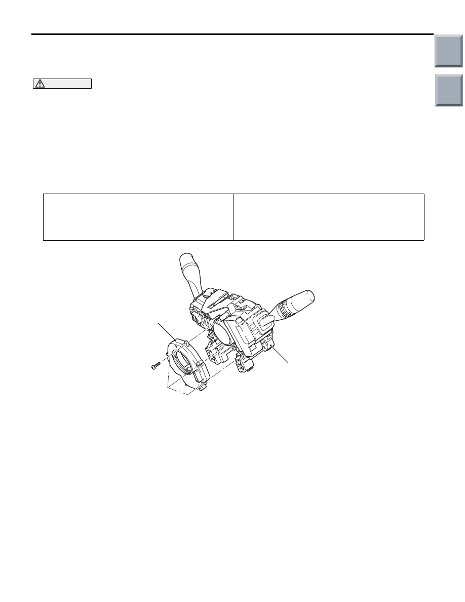
Removal steps
•
Position the front wheels in a straight
ahead direction.
1. Clock spring/column switch assembly
(Refer to GROUP 52B
− SRS Control
Unit
2. Steering wheel sensor
Removal steps (Continued)
Main
Index
Group
TOC