Mitsubishi Colt Ralliart. Manual - part 480


  Index      Mitsubishi     Mitsubishi Colt Ralliart - service repair manual


Search            


Content   ..  478  479  480  481   ..


Mitsubishi Colt Ralliart. Manual - part 480


COMBINATION METER

CHASSIS ELECTRICAL

54A-65

ON-VEHICLE SERVICE

CHECK THE SPEEDOMETER.

M1543000900995

CAUTION

Since the diagnosis code may be stored in the 
ABS-ECU when checking the speedometer with 
speedometer tester, erase the diagnosis code.

CAUTION

Do not accelerate or decelerate suddenly during 
servicing work.
1. Check that the current tyre inflation pressures 

meet the inflation pressure label.

AC105247AB

Wheel chocks

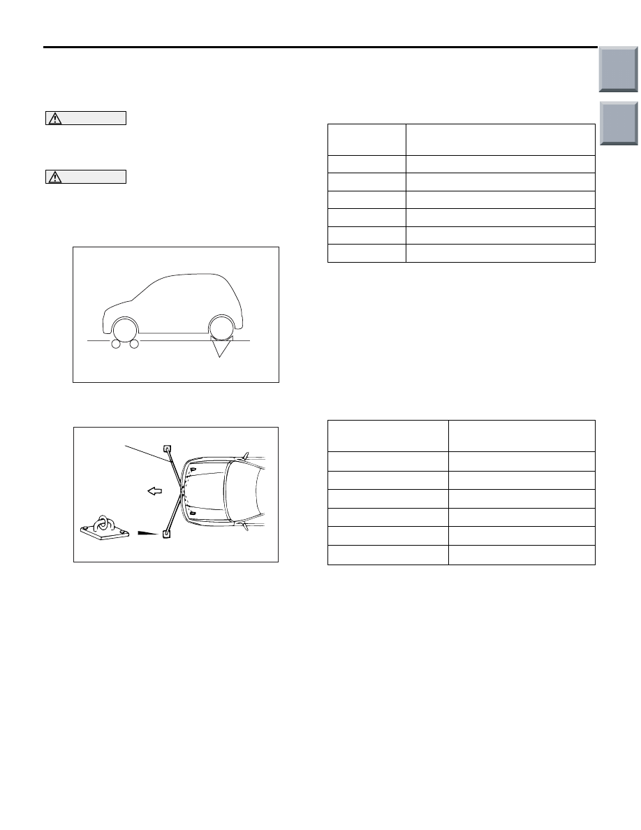
2. Chock the rear wheels and depress the parking 

brake pedal.

AC001288

Tension bar

Front

Anchor plate

AB

3. For prevention of front wheel lateral runout, install 

extension fittings on front towing eye and tie down 
hook, and install both ends of anchor plate.

4. For prevention of vehicle from starting out, install 

chain or wire (the other end of which is tightly 
fixed on rear towing eye) on the vehicle.

5. Check that the speedometer indicating range is 

within the standard value or the needle fluctuation 
is within the limit.

Standard value:

Speed km/h

Speedometer indicating 
tolerance km/h

20

20 - 24

40

40 - 44

80

80.5 - 85.5

120

121.5 - 127.5

160

162.5 - 169.5

200

203.5 - 211.5

Limit: Needle fluctuation (Vehicle speed is 35 
km/h or more) 

± 3 km/h

TACHOMETER CHECK

M1543001000791

Check that the tachometer indicating tolerance is 
within the standard value when the actuator tests 
(item No.85 and 86) are performed using M.U.T.-III.
NOTE: The value in parentheses is a reference 
value.

Standard value:

Engine speed r/min

Tachometer indicating 
tolerance r/min

700

± 70

(2,000)

(

± 80)

3,000

± 120

(4,000)

(

± 120)

5,000

± 120

6,000

± 120

FUEL TANK GAUGE UNIT CHECK

M1543001200944

Remove the fuel tank gauge unit and fuel tank pump 
and gauge unit assembly (Refer to GROUP 13C, 
Fuel Tank 

P.13C-5

).

Main

Index

Group

TOC

COMBINATION METER

CHASSIS ELECTRICAL

54A-66

NOMINAL RESISTANCE OF THE FUEL 
GAUGE UNIT

AC400048AB

Fuel gauge unit

Earth

 Position "E"

Position "F"

When float of the fuel gauge unit is in stopper posi-
tions "F" and "E", ensure that resistance between the 
fuel gauge unit terminal and earth terminal is within 
the standard value.

Standard value:

Float position

Gauge resistance 

Stopper position "F"

13.0 

± 1

Stopper position "E"

120.0 

± 1

When the float is moved slowly between stopper 
positions "F" and "E", ensure that the resistance is 
smoothly changing.

FUEL GAUGE UNIT FLOAT HEIGHT

AC400049AB

 Position "E"

Position "F"

A

B

When float is moved to contact the float arm on the 
stopper, ensure that stopper positions "F" (highest A) 
and "E" (lowest B) are within the standard value.

Standard value:

Float position

Float height mm

Stopper position "F" 
(highest A)

57.7

Stopper position "E" 
(lowest B)

215

Main

Index

Group

TOC

COMBINATION METER

CHASSIS ELECTRICAL

54A-67

REMOVAL AND INSTALLATION

M1543019800156

CAUTION

When the battery cable is disconnected or the combination meter is removed, the fuel gauge learned 
value will be erased. To let the display unit re-learn it, enter the vehicle speed (by driving the vehicle 
or entering simulated vehicle speed) and then stop the vehicle. Service on a level surface (If the vehi-
cle is inclined, the measurement value will go out).

AC314161AC

1

1

2

3

4

Removal steps 

1.

Steering column cover

2.

Lighting switch

3.

Combination meter bezel (Refer 
to GROUP 52A, Instrument Panel 
Assembly 

P.52A-3

).

<<

A

>>

4.

Combination meter assembly

Removal steps (Continued)

Main

Index

Group

TOC

COMBINATION METER

CHASSIS ELECTRICAL

54A-68

REMOVAL SERVICE POINT
<<A>>COMBINATION METER ASSEM-
BLY REMOVAL

AC208974AB

Turn the ignition switch to the ACC or ON position, 
and then engage the upper mounting part of combi-
nation meter between the steering wheel spoke. 
Rotate the steering wheel toward the arrow direction 
while pushing the combination meter gently to 
remove the combination meter.

DISASSEMBLY AND REASSEMBLY

M1543019900153

AC314153 AB

1

3

2

Disassembly steps 

1.

Glass

2.

Window plate

3.

Meter sub assembly

Disassembly steps (Continued)

Main

Index

Group

TOC


Content   ..  478  479  480  481   ..