Mitsubishi Colt Ralliart. Manual - part 478
 

  Index      Mitsubishi     Mitsubishi Colt Ralliart - service repair manual


Search            


Content   ..  476  477  478  479   ..


Mitsubishi Colt Ralliart. Manual - part 478


COMBINATION METER

CHASSIS ELECTRICAL

54A-57

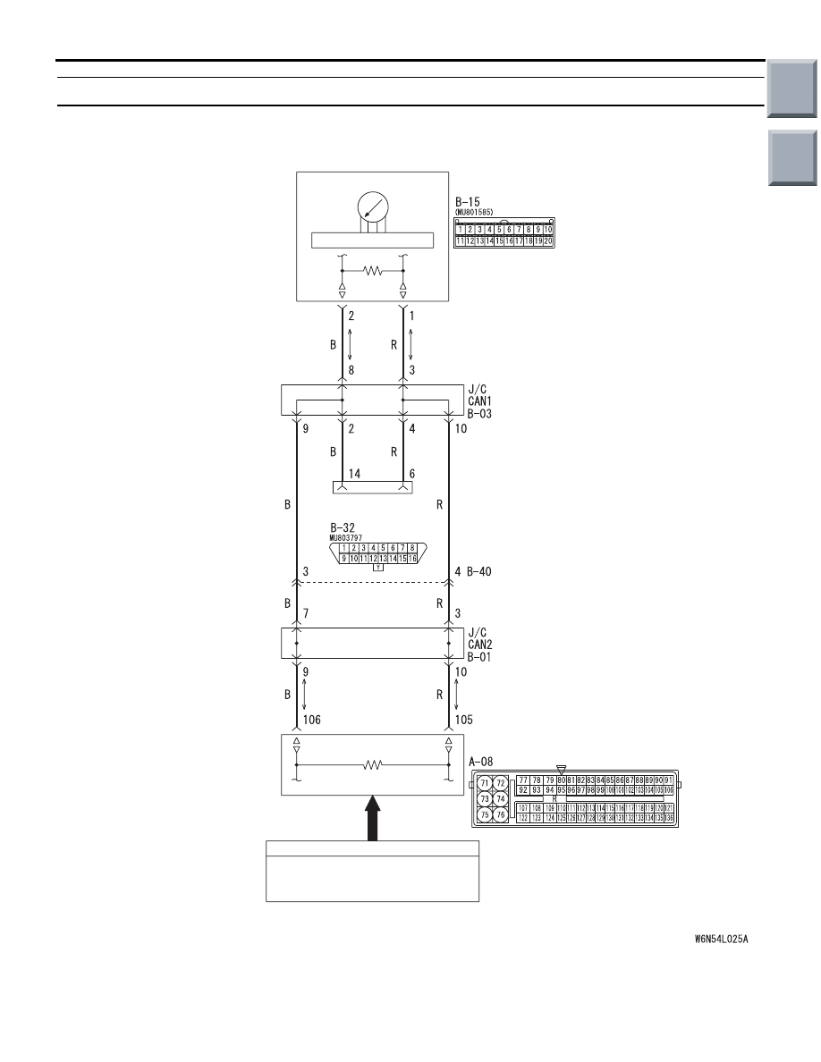
Inspection Procedure 10: Engine Coolant Temperature Gauge does not Work (Other Meters Work).

Engine Coolant Temperature Gauge Circuit

DIAGNOSIS 
CONNECTOR

INPUT SIGNAL

FRONT SIDE

COMBINATION 
METER

CPU

T/GA

SECONDARY SPEED SENSOR

ENGINE-ECU <M/T>
ENGINE-CVT-ECU <CVT>

Wire colour code
B : Black 
LG : Light green
G : Green
L: Blue 
W : White
Y: Yellow
SB : Sky blue
BR : Brown 
O : Orange
GR : Grey  
R : Red 
P : Pink  
V : Violet
PU: Purple

Main

Index

Group

TOC

COMBINATION METER

CHASSIS ELECTRICAL

54A-58

COMMENTS ON TROUBLE SYMPTOM

If only the engine coolant temperature gauge does 
not operate, the engine-ECU <M/T> or 
engine-CVT-ECU <CVT> system, the combination 
meter, the wiring harness or its connector may be 
defective.

POSSIBLE CAUSES

• Damaged harness wires and connectors

• Malfunction of engine-ECU <M/T> or 

engine-CVT-ECU <CVT>

• Malfunction of combination meter

DIAGNOSIS PROCEDURE

STEP 1. M.U.T.-III CAN bus diagnostics
Use the M.U.T.-III to diagnose the CAN bus lines.

Q: Is the check result satisfactory?

YES : 

Go to Step 2.

NO : 

Repair the CAN bus lines (Refer to GROUP 
54D, Diagnosis - Can Bus Diagnostics Table 

P.54D-13

). After diagnosing the CAN bus 

lines, go to Step 5.

STEP 2. M.U.T.-III other system diagnosis code
Check if an MPI system diagnosis code is set.

Q: Is the diagnosis code set?

YES : 

Diagnose MPI system. (Refer to GROUP 

13A <4A9>, Troubleshooting 

P.13A-20

, or 

GROUP 13B <4G1>, Troubleshooting 

P.13B-18

.) After diagnosing the MPI 

system, go to Step 5.

NO : 

Go to Step 3.

STEP 3. M.U.T.-III data list

• Item No.8C: Water thermometer (Refer to 

P.54A-59

.)

• Item No.8E: Water thermometer definite flag 

(Refer to 

P.54A-59

.)

Q: Is the check result satisfactory?

YES : 

Go to Step 4.

NO : 

Diagnose MPI system. (Refer to GROUP 
13A <4A9>, Troubleshooting 

P.13A-20

, or 

GROUP 13B <4G1>, Troubleshooting 

P.13B-18

.) After diagnosing the MPI 

system, go to Step 5.

STEP 4. M.U.T.-III actuator test

• Item No.88: Water temperature gauge:  0 °C

• Item No.89: Water temperature gauge:  85 °C

• Item No.8A: Water temperature gauge:  126 °C

OK: The water thermometer operates.

Q: Is the check result satisfactory?

YES : 

Go to Step 5.

NO : 

Replace combination meter and then go to 
step 5.

STEP 5. Retest the system.
Check to see that the engine coolant temperature 
gauge operates normally.

Q: Is the check result satisfactory?

YES : 

The procedure is complete.

NO : 

Go to Step 1.

Main

Index

Group

TOC

COMBINATION METER

CHASSIS ELECTRICAL

54A-59

DATA LIST REFERENCE TABLE

M1543007300916

The following items of the ECU input data can be 
read using M.U.T.-III.

Item No.

Check items

Check conditions

Normal conditions

80

Speedometer

Perform a test run of the 
vehicle.

Speedometer displayed value and 
M.U.T.-III displayed value agree with 
each other.

*

81

Speedometer (target 
value)

Perform a test run of the 
vehicle.

Speedometer displayed value and 
M.U.T.-III displayed value agree with 
each other.

*

82

Vehicle speed sensor 
malfunction flag

Ignition switch : ON

Without

83

Vehicle speed sensor 
definite flag

Ignition switch : ON

Set

84

Vehicle stopped flag

• Ignition switch : ON

• Vehicle speed 0 km/h 

Set

87

Tachometer

Start the engine.

Tachometer displayed value and 
M.U.T.-III displayed value agree with 
each other.

89

Fuel gauge

Fuel gauge unit resistance value and 
M.U.T.-III displayed value agree with 
each other.

8A

Fuel gauge (target value) −

Fuel gauge and M.U.T.-III displayed 
values agree with each other.

8C

Water thermometer

Ignition switch : ON

Water thermometer and M.U.T.-III 
displayed values agree with each 
other.

8E

Water thermometer 
definite flag

Ignition switch : ON

Set

90

Odometer

Odometer displayed value and 
M.U.T.-III displayed value agree with 
each other.

A0

Door-ajar warning light

All doors are closed

OFF

Any door is open

ON

A1

SRS warning lamp

OFF

A2

ABS warning lamp

OFF

A3

Hydraulic pressure 
warning lamp 

OFF

A4

Charging warning lamp

OFF

A5

Engine warning lamp

OFF

A6

Fuel reserve warning 
lamp

OFF

Main

Index

Group

TOC

COMBINATION METER

CHASSIS ELECTRICAL

54A-60

A7

Brake warning lamp

• Ignition switch : ON

• Parking brake : At 

release

OFF

• Ignition switch : ON

• Parking brake : 

OPERATION

ON

A8

Seat belt warning lamp

• Ignition switch : ON

• Driver's seatbelt : 

fastened

OFF

• Ignition switch : ON

• Driver's seatbelt : Not 

fastened

ON

A9

Electric power steering 
warning lamp

OFF

B1

Turn-signal indicator 
(RH)

Turn signal lamp : OFF 
or only left side lamp 
illuminates

OFF

Turn signal lamp : Right 
side lamp illuminates

ON

B2

Turn-signal indicator 
(LH)

Turn signal lamp : OFF 
or only right side lamp 
illuminates

OFF

Turn signal lamp : Left 
side lamp illuminates

ON

B3

Front fog lamp indicator

Fog lamp :  OFF

OFF

Fog lamp :  ON

ON

B4

High-beam indicator

Headlamps : OFF or low 
beam illuminates

OFF

Headlamps : High beam 
illuminates

ON

C1

CVT indicator: P

Shift position : Other than 
P position

OFF

Shift position : P position ON

C2

CVT indicator: R

Shift position : Other than 
R position

OFF

Shift position : R position ON

C3

CVT indicator: N

Shift position : Other than 
N position

OFF

Shift position : N position ON

C4

CVT indicator: D

Shift position : Other than 
D position

OFF

Shift position : D position ON

C5

CVT indicator: Ds

Shift position : Other than 
Ds position

OFF

Shift position : Ds 
position

ON

Item No.

Check items

Check conditions

Normal conditions

Main

Index

Group

TOC


Content   ..  476  477  478  479   ..