Mitsubishi Colt Ralliart. Manual - part 476
COMBINATION METER
CHASSIS ELECTRICAL
54A-49
Inspection Procedure 6: Speedometer does not Work (Other Meters Work).
Inspection Procedure 7: The Fuel Gauge Needle Moves Excessively.
DIAGNOSIS
CONNECTOR
INPUT SIGNAL
FRONT SIDE
COMBINATION
METER
CPU
SPEED
SECONDARY SPEED SENSOR
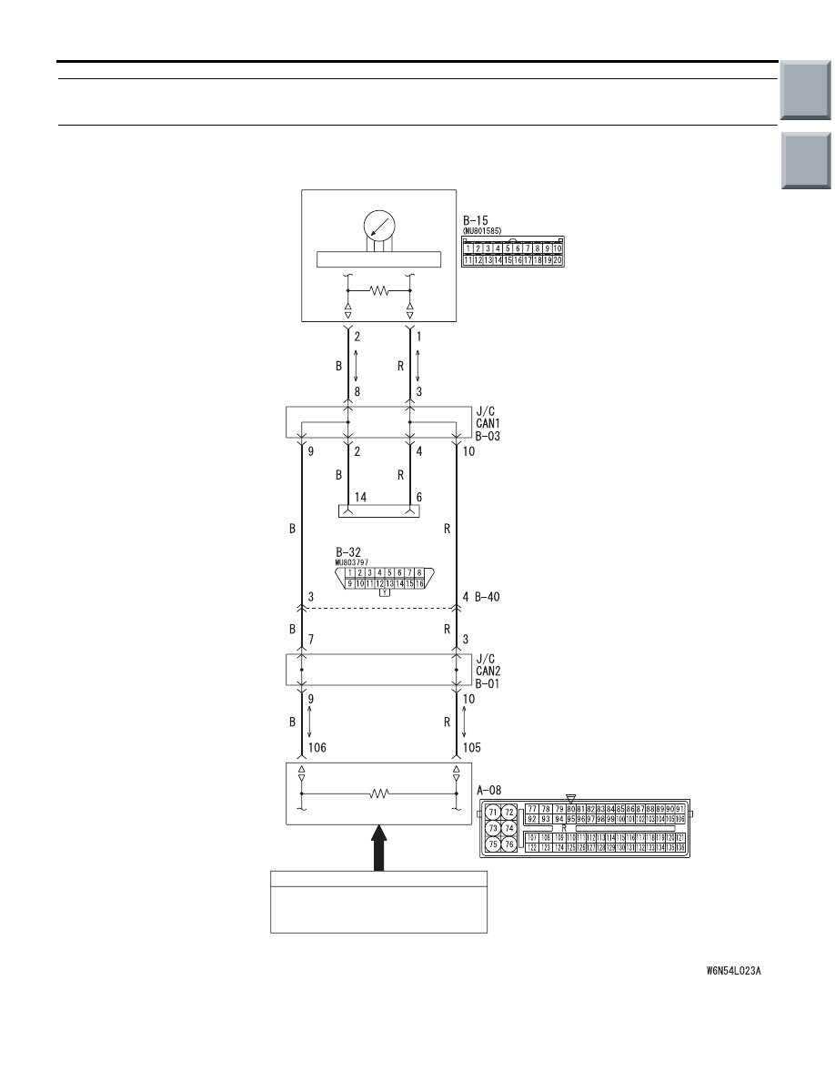
Speedometer Circuit
ENGINE-ECU <M/T>
ENGINE-CVT-ECU <CVT>
Wire colour code
B : Black
LG : Light green
G : Green
L: Blue
W : White
Y: Yellow
SB : Sky blue
BR : Brown
O : Orange
GR : Grey
R : Red
P : Pink
V : Violet
PU: Purple
Main
Index
Group
TOC