Mitsubishi Colt Ralliart. Manual - part 203


  Index      Mitsubishi     Mitsubishi Colt Ralliart - service repair manual


Search            


Content   ..  201  202  203  204   ..


Mitsubishi Colt Ralliart. Manual - part 203


VALVE BODY ASSEMBLY, SENSORS

CVT

23A-155

VALVE BODY ASSEMBLY, SENSORS

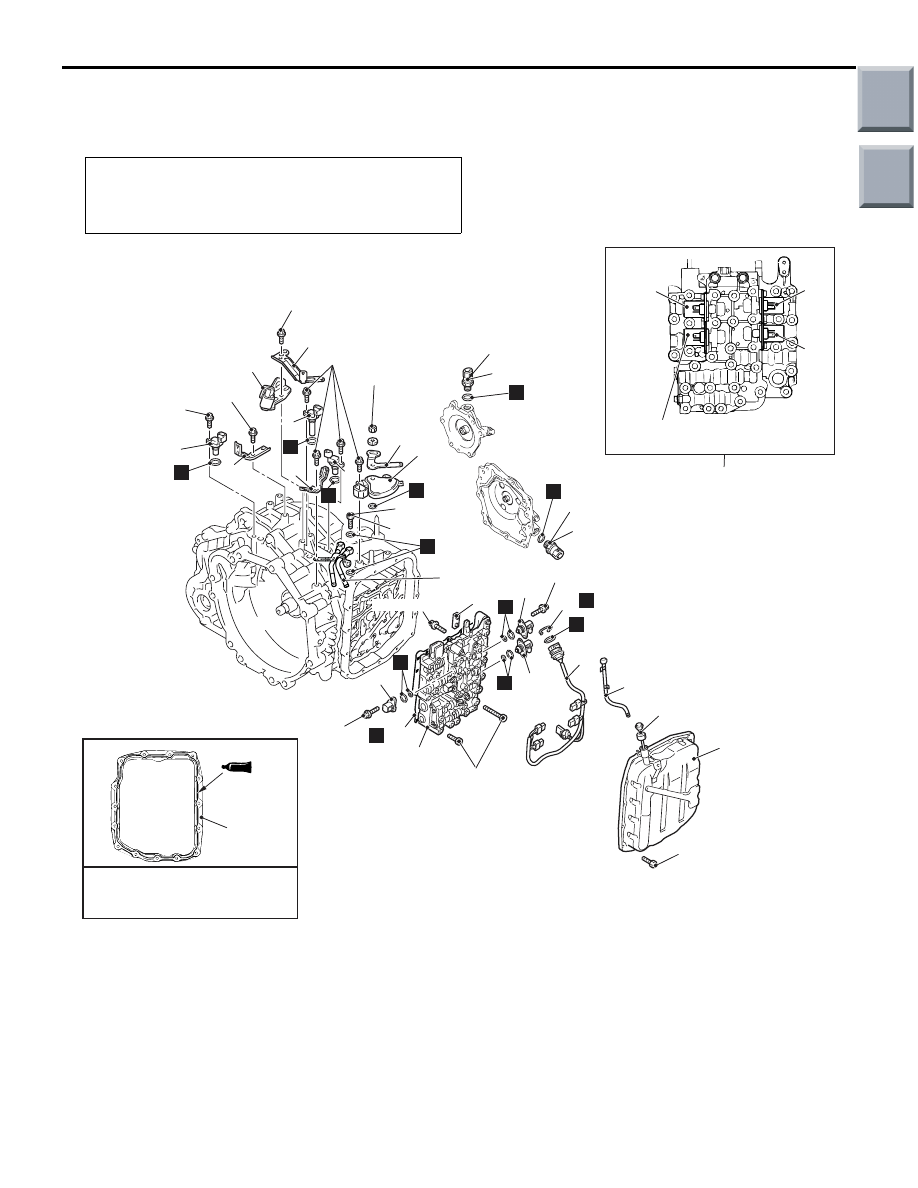
REMOVAL AND INSTALLATION

M1231204000150

Pre-removal and Post-installation Operation
• Air cleaner assembly removal and installation (Refer to 

GROUP 15, Air Cleaner 

P.15-5

).

• Battery and battery tray removal and installation

AC404206

14

Sealant: 
MITSUBISHI GENUINE PART 
MD974421 or equivalent

(dia. 2.5 mm)

21

22

20

Shift control solenoid valve

10

19 ± 3 N·m

11

19 ± 3 N·m

22 ± 3 N·m

5

6

11 ± 1 N·m

7

1

1

1

2

23 ± 3 N·m

11 ± 1 N·m

9

4

AD

11 ± 1 N·m

11 ± 1 N·m

18

15

21

6.0 ± 1.0 N·m

22

20

6.0 ± 1.0 N·m

16

N

17

12

14

15

6.0 ± 1.0 N·m

23 ± 3 N·m

8

3

13

19

30 ± 3 N·m

N

N

N

N

N

N

N

N

N

N

N

N

Bracket removal steps 

1.

Harness bracket

2.

Control cable bracket
Oil cooler pipe removal steps 

Oil cooler hose connection

3.

Eye bolt

4.

Oil cooler pipe
Inhibitor switch removal steps 

Transmission control cable 
(transmission side)

5.

Manual control lever

6.

Inhibitor switch
Sensor removal steps 

2.

Control cable bracket

Harness connector connection

7.

Turbine speed sensor

8.

Primary speed sensor

9.

Secondary speed sensor

<<

A

>>

10. Line pressure sensor

Inhibitor switch removal steps 

Main

Index

Group

TOC

VALVE BODY ASSEMBLY, SENSORS

CVT

23A-156

Front under cover panel assembly 
(Refer to GROUP 51, Front 
Bumper Assembly and Radiator 
Grille 

P.51-2

).

<<

A

>>

11. Primary pressure sensor

Transmission fluid draining and 
refilling (Refer to 

P.23A-133

).

6.

Inhibitor switch

Cooling fan, cooling fan motor and 
shroud assembly (Refer to GROUP 
14, Radiator 

P.14-22

).

12. Oil level gauge

>>

C

<<

13. Breather hose assembly
14. Valve body cover

<<

B

>>

>>

B

<<

15. Valve body assembly
16. Snap ring
17. Solenoid valve harness and CVT oil 

temperature sensor
Oil strainer removal steps 

Harness connector connection

Transmission fluid draining and 
refilling (Refer to 

P.23A-133

).

6.

Inhibitor switch

Cooling fan, cooling fan motor and 
shroud assembly (Refer to GROUP 
14, Radiator 

P.14-22

).

12. Oil level gauge

>>

C

<<

13. Breather hose assembly

14. Valve body cover

<<

B

>>

>>

B

<<

15. Valve body assembly
18. Oil strainer
19. Inside separating plate

Solenoid valve removal steps 

Harness connector connection

Transmission fluid draining and 
refilling (Refer to 

P.23A-133

).

6.

Inhibitor switch

Cooling fan, cooling fan motor and 
shroud assembly (Refer to GROUP 
14, Radiator 

P.14-22

).

12. Oil level gauge

>>

C

<<

13. Breather hose assembly
14. Valve body cover

<<

B

>>

>>

B

<<

15. Valve body assembly
17. Solenoid valve harness and CVT oil 

temperature sensor

<<

C

>>

>>

A

<<

20. Line pressure control solenoid 

valve

<<

C

>>

>>

A

<<

21. Damper clutch control solenoid 

valve

<<

C

>>

>>

A

<<

22. Clutch pressure control solenoid 

valve

Sensor removal steps 

Oil strainer removal steps 

Main

Index

Group

TOC

VALVE BODY ASSEMBLY, SENSORS

CVT

23A-157

REMOVAL SERVICE POINTS
<<A>> LINE PRESSURE SENSOR/PRI-
MARY PRESSURE SENSOR REMOVAL

CAUTION

The line pressure sensor and primary pressure 
sensor incorporate integrated circuit. If the sen-
sor connector is disconnected, be careful not to 
let water enter the sensor-side connector.

<<B>> VALVE BODY ASSEMBLY 
REMOVAL

AC207317AC

CAUTION

Do not remove the two bolts indicated by arrow 
in the figure.
Remove the 34 valve body assembly mounting bolts.

<<C>> SOLENOID VALVE REMOVAL

CAUTION

The shift control solenoid valve cannot be 
removed or replaced as individual part. If the 
shift control solenoid valve must be replaced, 
replace it as a valve body assembly.
Paint a white mark so that the installation position 
can be identified.

INSTALLATION SERVICE POINTS
>>A<< SOLENOID VALVE INSTALLATION

AC207318 AB

Damper clutch control 
solenoid valve

Clutch pressure 
control solenoid 
valve

Shift control 
solenoid valve

Line pressure 
control solenoid 
valve

Tighten each solenoid valve to the specified torque 
as identified by paint mark made during removal.

Tightening torque: 6.0 

± 1.0 Nm

Main

Index

Group

TOC

VALVE BODY ASSEMBLY, SENSORS

CVT

23A-158

>>B<< VALVE BODY ASSEMBLY 
INSTALLATION

AC207317AB

Tighten the 34 valve body assembly mounting bolts 
to the specified torque.

Tightening torque: 11 

± 1 Nm

>>C<< BREATHER HOSE ASSEMBLY 
INSTALLATION

AC403667AD

Clamp

Breather
hose assembly

Clip

Air cleaner

Install  each clamp of breather hose assembly to the 
hole of air cleaner securely so that the claw of clip 
faces towards the front of the vehicle.

Main

Index

Group

TOC


Content   ..  201  202  203  204   ..