Mitsubishi Colt Ralliart. Manual - part 202
TRANSMISSION ASSEMBLY
CVT
23A-151
5.
CVT control solenoid valve
assembly connector
6.
Primary speed sensor connector
7.
Turbine speed sensor connector
8.
Secondary speed sensor connector
9.
Line pressure sensor connector
Removal steps (Continued)
<<
A
>>
10. Cable band
<<
B
>>
11. Transmission assembly upper part
coupling bolt
12. ATF warmer connection
AC403792AD
13
14
16
20
18
17
21
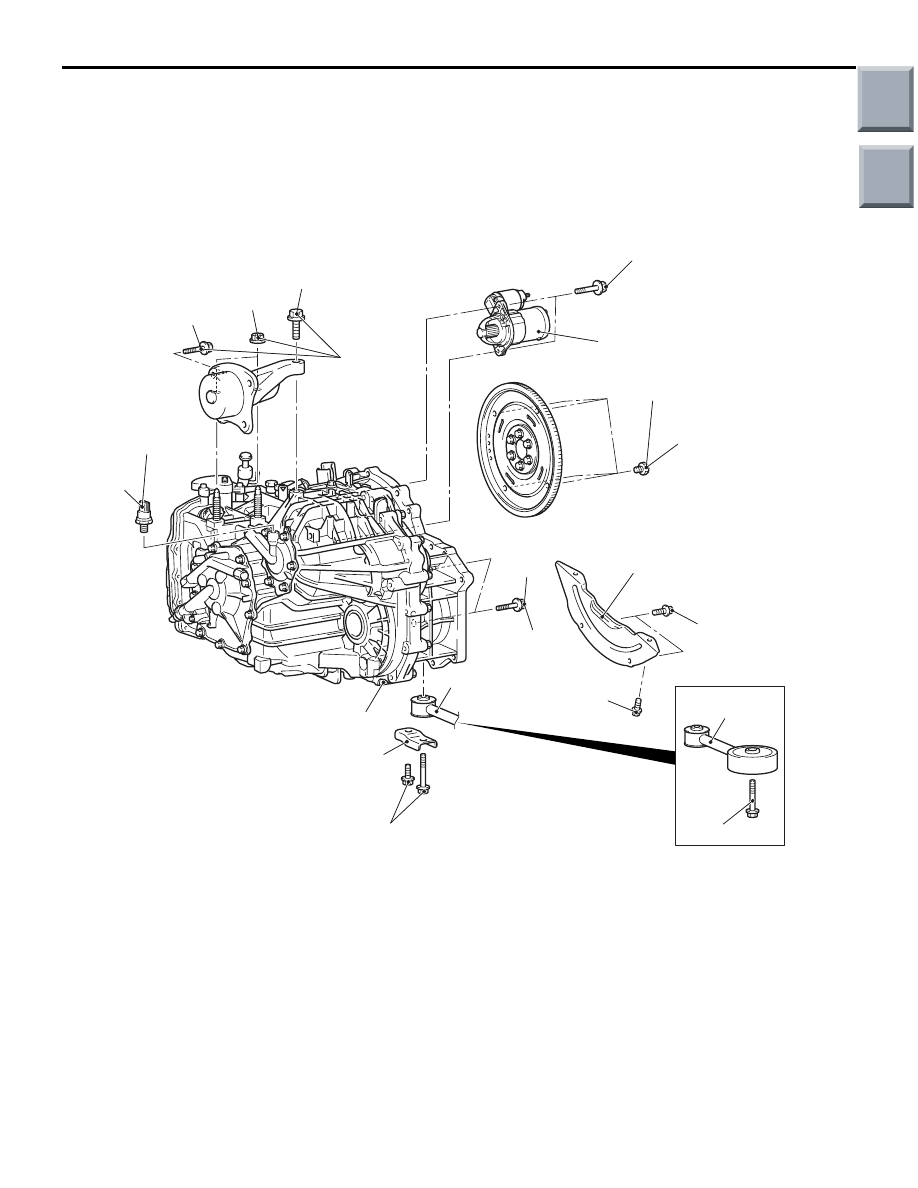
90 ± 10 N·m*
6.7 ± 1.3 N·m
6.7 ± 1.3 N·m
23 ± 3 N·m
19 ± 3 N·m
45 ± 10 N·m
63 ± 7 N·m
63 ± 7 N·m
90 ± 10 N·m*
14
15
49 ± 3 N·m
24 ± 3 N·m
19
Removal steps
13. Engine mounting stay
14. Engine roll stopper rod assembly
15 Bell housing cover
<<
C
>>
16. Torque converter and drive plate
coupling bolt
17. Secondary pressure sensor
•
Raise the engine and transmission
assembly to the position where the
engine weight is not applied to the
transmission mounting insulator.
18. Transmission mounting insulator
coupling bolt and nut
<<
D
>>
•
Holding the engine assembly
19. Starter
20. Transmission assembly lower part
coupling bolt
>>
A
<< 21. Transmission assembly
Removal steps (Continued)
Removal steps (Continued)
Main
Index
Group
TOC