Mitsubishi Colt Ralliart. Manual - part 201


  Index      Mitsubishi     Mitsubishi Colt Ralliart - service repair manual


Search            


Content   ..  199  200  201  202   ..


Mitsubishi Colt Ralliart. Manual - part 201


TRANSMISSION CONTROL

CVT

23A-147

REMOVAL SERVICE POINTS
<<A>> KEY INTERLOCK ROD REMOVAL

CAUTION

Do not bend the key interlock rod cable.
Turn the ignition switch to the ACC position and then 
pull the key interlock rod out from the ignition key cyl-
inder.

INSTALLATION SERVICE POINTS
>>A<< TRANSMISSION CONTROL 
CABLE (TRANSMISSION SIDE) INSTAL-
LATION

AC103395AD

Adjusting nut

Transmission
control cable

1. Shift the selector lever and manual control lever to 

the N position.

2. Gently push the transmission control cable in the 

direction of the arrow (with a force of 
approximately 5 N) to tighten the adjusting nut to 
the specified torque.

Tightening torque: 12 

± 2 Nm

>>B<< TRANSMISSION CONTROL 
CABLE (SELECTOR LEVER SIDE) 
INSTALLATION

Ensure that the transmission control cable is con-
nected securely.

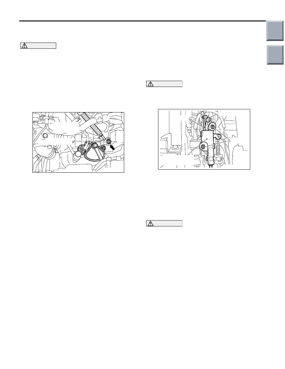
>>C<< SHIFT LOCK CALBLE UNIT/SHIFT 
LOCK ROD INSTALLATION

CAUTION

Do not bend the shift lock cable.
1. Shift the selector lever to the P position and turn 

the ignition switch to the LOCK (OFF) position.

AC208298

AB

Bolt

Rod

Lock cam

Shift lock cable 
unit

2. After installing the shift lock rod to the lock cam of 

the selector lever assembly, tighten the bolts of 
the shift lock cable unit to the specified torque.

Tightening torque: 5.0 

± 1.0 Nm

>>D<< KEY INTERLOCK ROD 
INSTALLATION

CAUTION

Do not bend the key interlock rod cable.
Turn the ignition switch to the ACC position and then 
install the key interlock rod through the ignition key 
cylinder.

Main

Index

Group

TOC

CVT KEY INTERLOCK AND SHIFT LOCK MECHANISMS

CVT

23A-148

CVT KEY INTERLOCK AND SHIFT LOCK MECHANISMS

REMOVAL AND INSTALLATION

M1231203400144

CAUTION

When removing and installing the shift lock cable unit, be careful not to hit the SRS-ECU.

Pre-removal Operation
• Steering column lower cover and instrument lower panel 

removal (Refer to GROUP 52A, Instrument Panel Assem-

bly 

P.52A-3

).

Post-installation Operation
• Key interlock and shift lock mechanism check (Refer to 

P.23A-144

).

• Selector lever operation check (Refer to 

P.23A-143

).

• Steering column lower cover and instrument lower panel 

installation (Refer to GROUP 52A, Instrument Panel 

Assembly 

P.52A-3

).

AC208300AB

1

2

4

5.0 ± 1.0 N·m

3

Removal steps 

Connectors and clamps around 
steering column assembly

1.

Shift lock cable connection

<<

A

>> >>

B

<< 2.

Key interlock rod connection

>>

A

<< 3.

Shift lock rod connection

>>

A

<< 4.

Shift lock cable unit

Removal steps (Continued)

Main

Index

Group

TOC

CVT KEY INTERLOCK AND SHIFT LOCK MECHANISMS

CVT

23A-149

REMOVAL SERVICE POINTS
<<A>> KEY INTERLOCK ROD REMOVAL

CAUTION

Do not bend the key interlock rod cable.
Turn the ignition switch to the ACC position and then 
pull the key interlock rod out from the ignition key cyl-
inder.

INSTALLATION SERVICE POINTS
>>A<< SHIFT LOCK CALBLE UNIT/SHIFT 
LOCK ROD INSTALLATION

CAUTION

Do not bend the shift lock cable.
1. Shift the selector lever to the P position and turn 

the ignition switch to the LOCK (OFF) position.

AC208298

AB

Bolt

Rod

Lock cam

Shift lock cable 
unit

2. After installing the shift lock rod to the lock cam of 

the selector lever assembly, tighten the bolts of 
the shift lock cable unit to the specified torque.

Tightening torque: 5.0 

± 1.0 Nm

>>B<< KEY INTERLOCK ROD 
INSTALLATION

CAUTION

Do not bend the key interlock rod cable.
Turn the ignition switch to the ACC position and then 
install the key interlock rod to the ignition key cylin-
der.

Main

Index

Group

TOC

TRANSMISSION ASSEMBLY

CVT

23A-150

TRANSMISSION ASSEMBLY

REMOVAL AND INSTALLATION

M1231203600201

CAUTION

*

: Indicates parts which should be temporarily tightened, and then fully tightened after placing the 

vehicle on the earth and loading the full weight of the engine on the vehicle body.

Pre-removal Operation
• Front Under Cover Panel AssemblyRemoval (Refer to 

GROUP 51, Front Bumper Assembly and Radiator Grille 

P.51-2

).

• Transmission Fluid Draining (Refer to 

P.23A-133

).

• Air Cleaner Assembly Removal (Refer to GROUP 15 

P.15-5

).

• Battery and Battery Tray Removal.
• Wiper Arm and Blade Assembly and Front Deck Garnish 

Removal (Refer to GROUP 51, Windshield Wiper 

P.51-29

).

• Cowl Top Panel Removal (Refer to GROUP 42, Loose 

Panel 

P.42-81

).

• Front Exhaust Pipe Removal (Refer to GROUP 15, 

Exhaust Pipe and Main Muffler 

P.15-19

).

• Driveshaft Removal (Refer to GROUP 26 

P.26-16

).

Post-installation Operation
• Driveshaft Installation (Refer to GROUP 26 

P.26-16

).

• Front Exhaust Pipe Installation (Refer to GROUP 15, 

Exhaust Pipe and Main Muffler 

P.15-19

).

• Cowl Top Panel Installation (Refer to GROUP 42, Loose 

Panel 

P.42-81

).

• Wiper Arm and Blade Assembly and Front Deck Garnish 

Installation (Refer to GROUP 51, Windshield Wiper 

P.51-29

).

• Battery and Battery Tray Installation.

• Air Cleaner Assembly Installation (Refer to GROUP 15 

P.15-5

).

• Front Under Cover Panel Assembly Installation (Refer to 

GROUP 51, Front Bumper Assembly and Radiator Grille 

P.51-2

).

• Transmission Fluid Refilling (Refer to 

P.23A-133

)

AC402909AF

1

2

3

11

12

23 ± 3 N·m

12 ± 2 N·m

48 ± 6 N·m

4

5

6

9

8

7

10

N

Removal steps 

1.

Transmission control cable 
connection

2.

Battery earth

3.

Primary pressure sensor harness 
connector

4.

Inhibitor switch connector

Removal steps (Continued)

Main

Index

Group

TOC


Content   ..  199  200  201  202   ..