Mitsubishi Colt Ralliart. Manual - part 204
ATF WARMER (ATF COOLER)
CVT
23A-159
ATF WARMER (ATF COOLER)
REMOVAL AND INSTALLATION
M1231204800048
Pre-removal and Post-installation Operation
• Air cleaner intake duct (Refer to GROUP 15 − Air Cleaner
).
• Engine coolant draining and refilling (Refer to GROUP 14
− On-vehicle Service − Engine Coolant Replacement
).
• Transmission fluid refilling (Refer to
AC403913
1
2
3
4
5
6
7
AC
23 ± 3 N·m
23 ± 3 N·m
8
9
N
1.5 ± 0.3 N·m
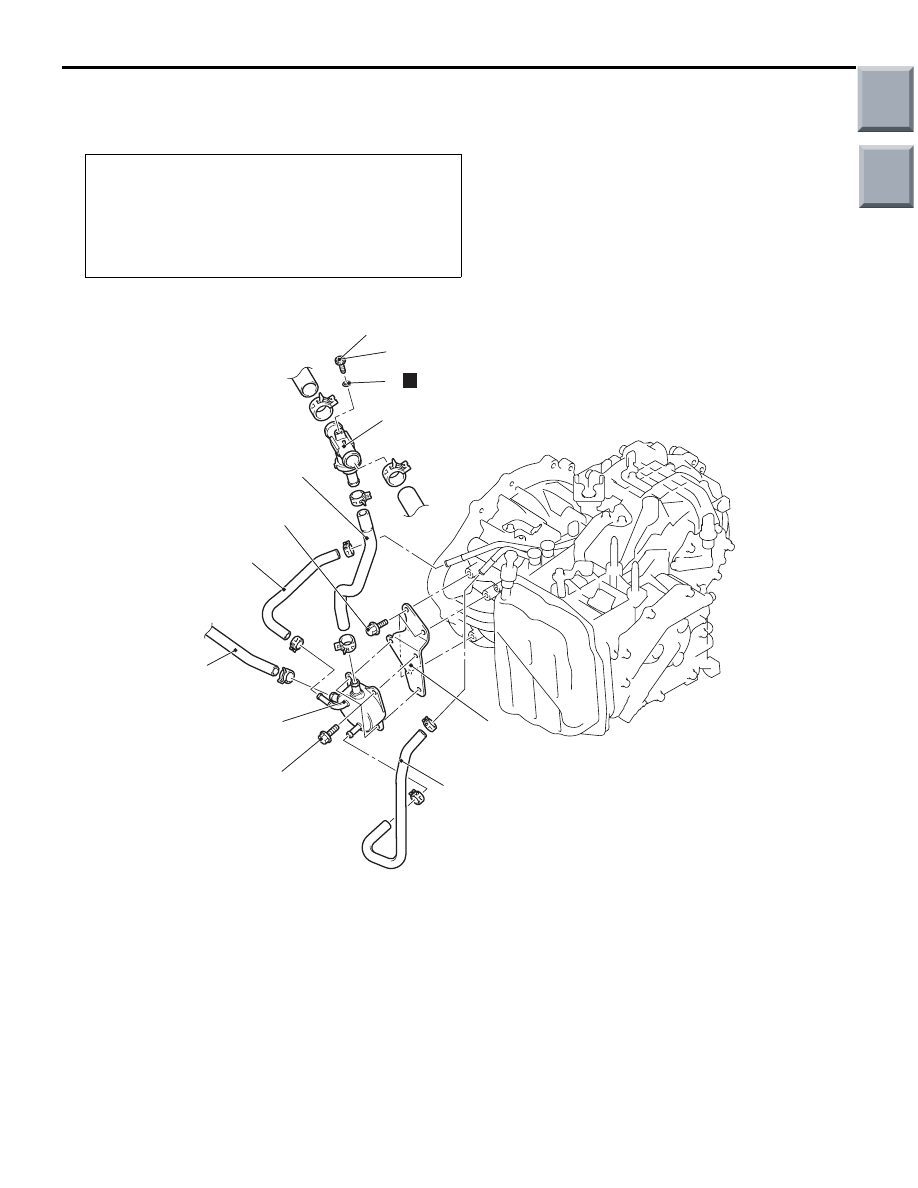
Removal steps
1.
Coolant feed hose
2.
Coolant return hose
3.
ATF feed hose
4.
ATF return hose
5.
ATF warmer (ATF cooler)
6.
ATF warmer (ATF cooler) bracket
7.
Thermo valve
8.
Breather plug
9.
O-ring
Removal steps (Continued)
Main
Index
Group
TOC