Mitsubishi Colt Ralliart. Manual - part 135
 

  Index      Mitsubishi     Mitsubishi Colt Ralliart - service repair manual


Search            


Content   ..  133  134  135  136   ..


Mitsubishi Colt Ralliart. Manual - part 135


HOW TO READ WIRING DIAGRAMS

GENERAL <ELECTRICAL>

00E-7

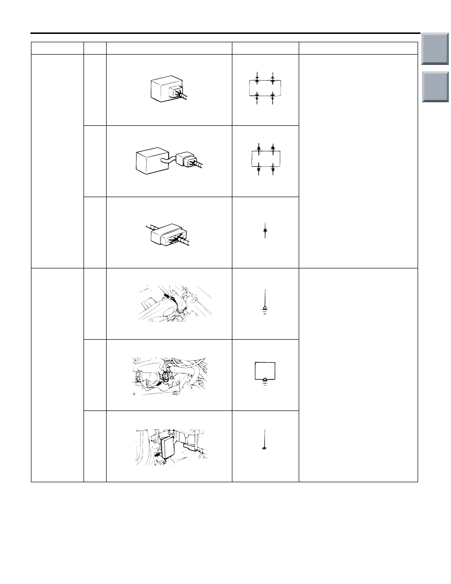
Connector 
connection 
marking

3

ACX01260 AD

Direct connection type

ACX01261

Connection between a device 
and the harness is either by 
direct insertion in the device 
(direct connection type) or by 
connection with a harness 
connector furnished on the 
device side (harness 
connection type). The two types 
are indicated as illustrated.

4

ACX01262 AD

Harness connection type

ACX01263

5

ACX01264AD

Intermediate connector

ACX01265

Earth 
marking

6

AC208448

AB

Body earth

ACX01274

Earthing is either by body earth, 
device earth or control unit 
interior earth. These are 
indicated as illustrated.

7

AC208449

AB

Device earth

ACX01276

8

AC208450

AB

Earth in control unit

ACX01278

Item

No.

Connector/Earthing

Symbol

Contents

Main

Index

Group

TOC

HOW TO READ WIRING DIAGRAMS

GENERAL <ELECTRICAL>

00E-8

WIRE COLOUR CODE

M1001008000195

Wire colours are identified by the following colour 
codes.

Code

Wire colour

Code

Wire colour

Code

Wire colour

Code

Wire colour

B

Black

L

Blue

PU

Purple

V

Violet

BR

Brown

LG

Light green

R

Red

W

White

G

Green

O

Orange

SB

Sky blue

Y

Yellow

GR

Grey

P

Pink

SI

Silver

ACX01279 AE

<F>

1.25

G

B

1

2

3

4

Example:

If a cable has two colours, the first of the two colour 
code characters indicates the basic colour (colour of 
the cable coating) and the second indicates the 
marking colour.

No.

Meaning

1

<F>: Flexible wire
<T>: Twisted wire

2

Wire size (mm

2

)*

3

Basic colour (colour of the cable coating)

4

Marking colour

NOTE: 


*: No code indicates 0.5 mm

2

. Cable colour code in 

parentheses indicates 0.3 mm

2

.

Main

Index

Group

TOC

HOW TO READ WIRING DIAGRAMS

GENERAL <ELECTRICAL>

00E-9

ABBREVIATION SYMBOLS

M1001008100459

The abbreviation symbols used in wiring diagrams are defined below.

1. For system name

Abbreviation 
symbol

Meaning

Abbreviation 
symbol

Meaning

ABS

Anti-skid braking system

INVECS

Intelligent and innovative vehicle 
electronic control system

ASC

Active stability control system

J/B

Junction block

CAN

Controller area network

J/C

Joint connector

CVT

Continuously variable transmission

M/T

Manual transmission

SRS

Supplemental restraint system

2. For combination meter

Abbreviation 
symbol

Meaning

Abbreviation 
symbol

Meaning

ABS

Anti-skid braking system warning 
lamp

ODO

Odometer

ASC

ASC indicator lamp

OIL

Engine oil pressure warning lamp

ASC OFF

ASC OFF indicator lamp

P, R, N, D, Ds, L Shift lever position indicator lamp

BEAM

High beam indicator lamp

SEAT BELT

Seat belt warning lamp

BRAKE

Brake warning lamp

SPEED

Speedometer

CHECK 
ENGINE

Check engine warning lamp

SRS

Supplemental restraint system 
warning lamp

CHG

Charging warning lamp

DOOR

Door-ajar warning lamp

T/GA

Engine coolant temperature gauge

EPS

EPS warning lamp

TACHO

Tachometer

F/GA

Fuel gauge

TAIL

Tail lamp indicator lamp

FOG

Fog indicator lamp

TRIP

Tripmeter

FUEL

Low fuel warning lamp

TURN (LH)

Turn-signal indicator lamp, hazard 
warning indicator lamp

LCD

Liquid crystal display

TURN (RH)

Main

Index

Group

TOC

HOW TO READ WIRING DIAGRAMS

GENERAL <ELECTRICAL>

00E-10

3. For switch and relay

Name of switches 
and relays

Abbreviation 
symbol

Operation

Blower switch

LO

Blower operates at low speed

ML

Blower operates at medium low

MH

Blower operates at medium high

HI

Blower operates at high

Dimmer passing switch LO

Low beams ON

HI

High beams ON

PASS

High beams ON

Door lock actuator

LOCK

Door lock

UNLOCK

Door unlock

Ignition switch

LOCK

When turned to the LOCK position, no circuits will start

ACC

When turned to the ACC (ACCESSORY) or ON position, the 
power circuit will start

IG2

When at the ST (START) position, the power circuit will not start 
functioning

IG1

Even when at the ST (START) position, the power circuit will start

ST

Only when turned to the ST (START) position, the power circuit 
will start

Inhibitor switch

P

Selector lever is at the P (PARKING) position

R

Selector lever is at the R (REVERSE) position

N

Selector lever is at the N (NEUTRAL) position

D

Selector lever is at the D (DRIVE) position

Ds

Selector lever is at the Ds (DOWN SHIFT and DRIVE SPORTY) 
position

L

Selector lever is at the L (LOW) position

Lighting switch

HEAD

Headlamps ON

TAIL

Tail, position, licence plate and illumination lamps ON

Others

ON

Switched ON

OFF

Switched OFF

Power window switch

UP

Window closes

DOWN

Window opens

AUTO DOWN

Window is easily opened with one action

LOCK

Prevents all switches other than the main switch from operating 
the power windows

UNLOCK

Every switch can open or close the respective window

Remote controlled 
mirror switch

LH

LH mirror operates

RH

RH mirror operates

Room lamp

DOOR

Room lamp ON when a door is open

Main

Index

Group

TOC


Content   ..  133  134  135  136   ..