Mitsubishi Colt Ralliart. Manual - part 10
AC405872AD
1
7
5
4
3
6
6
6
6
12 ± 2 N·m
7
8
9
10
11
11
2
12 ± 2 N·m
12 ± 2 N·m
9.0 ± 2.0 N·m
9.0 ± 2.0 N·m
9.0 ± 2.0 N·m
9.0 ± 2.0 N·m
13 ± 2 N·m
12 ± 2 N·m
12
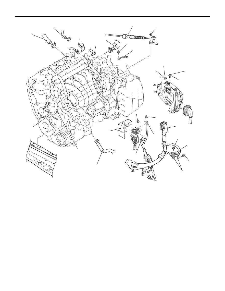
Removal steps
>>
D
<<
•
Initialisation <Installation only>
1.
Brake booster vacuum hose
connection
2.
Transmission control cable
connection
3.
Earth connection
4.
Earth cable connection
5.
Fusible link box cover
6.
Control harness connection
7.
Engine-CVT-ECU mounting bolt
and nut
8.
Engine-CVT-ECU connector
9.
Purge solenoid hose connection
<<
A
>>
>>
C
10. Fuel high-pressure hose
connection
11. Heater hose connection
12. Water hose connection
ENGINE ASSEMBLY
ENGINE MECHANICAL <4A9>
11A-37
Removal steps (Continued)