Mitsubishi Colt Ralliart. Manual - part 11


  Index      Mitsubishi     Mitsubishi Colt Ralliart - service repair manual


Search            


Content   ..  9  10  11  12   ..


Mitsubishi Colt Ralliart. Manual - part 11


ENGINE ASSEMBLY

ENGINE MECHANICAL <4A9>

11A-41

<<D>> TRANSMISSION MOUNTING 
INSULATOR CONNECTING BOLT AND 
NUT/ENGINE MOUNTING INSULATOR 
CONNECTING BOLT AND NUT/ENGINE 
MOUNTING INSULATOR REMOVAL

AC403079

1. Place a cart below the engine and transmission 

assembly.

2. Lower the lift to the position where the weight of 

the engine and transmission assembly is not 
applied to the transmission mounting insulator 
and the engine mounting insulator.

3. Remove the self-locking nuts, transmission 

mounting insulator mounting bolt and engine 
mounting insulator mounting bolts.

CAUTION

Because the engine assembly is installed with 
tilted toward the rear side, support the engine 
and transmission assembly after removing the 
engine mounting insulator.
4. Remove the engine mounting insulator.

<<E>> ENGINE AND TRANSMISSION 
ASSEMBLY REMOVAL

1. Confirm that the cable, the hose, and the harness 

connector are all disconnected.

CAUTION

Do not bend the fuel high-pressure hose.
2. Raise the body slowly with a lift, and remove the 

engine and transmission assembly.

<<F>> TRANSMISSION CONNECTING 
BOLT/ENGINE ASSEMBLY REMOVAL

AC311780

AB

MB991454

MB991527

1. Install the chain of special tool engine hanger 

balancer (MB991454) and special tool engine 
hanger (MB991527), and set the chain block.

2. Remove the transmission assembly connecting 

bolts.

CAUTION

• When lifting the engine assembly, operate 

with care not to lift the transmission assem-
bly.

• When working, make sure that the torque 

converter will not be detached with the 
engine.

3. Lift the engine assembly slowly using the chain 

block, and remove the transmission assembly 
when the engine assembly is lifted a little.

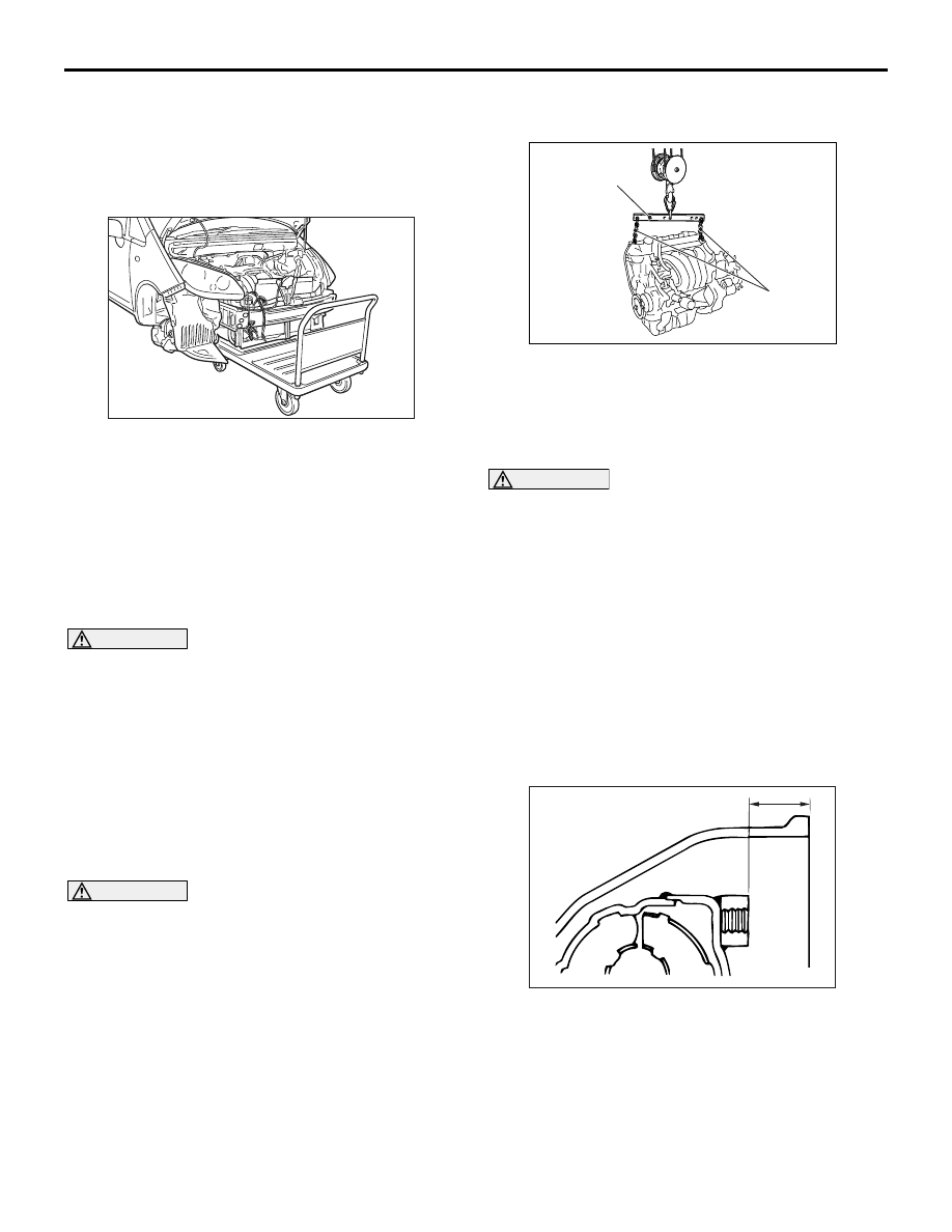
INSTALLATION SERVICE POINTS
>>A<< ENGINE ASSEMBLY INSTALLA-
TION

AC105798AB

A

Before installing the engine assembly, ensure that 
the dimension A from the torque converter housing 
end to the front end of the torque converter mounting 
boss shall be minimum 12.2 mm and the torque con-
verter is securely installed.

ENGINE ASSEMBLY

ENGINE MECHANICAL <4A9>

11A-42

>>B<< ENGINE AND TRANSMISSION 
ASSEMBLY/ENGINE MOUNTING 
INSULATOR/ENGINE MOUNTING 
INSULATOR CONNECTING BOLT AND 
NUT/TRANSMISSION MOUNTING 
INSULATOR CONNECTING BOLT AND 
NUT INSTALLATION

AC403079

1. Place the engine and transmission assembly on 

the cart below the lifted vehicle.

2. Lower the lift to the position where the mounting 

bolts of the engine mounting insulator and the 
transmission mounting insulator, and the 
self-locking nuts are installed.

3. Install the engine mounting insulator.
4. Tighten the new self-locking nuts of engine 

mounting insulator and transmission mounting 
insulator to the specified torque, and tighten the 
new mounting bolts of engine mounting insulator 
and transmission mounting insulator to the 
specified torque.

Tightening torque:

68 

± 7 Nm <Engine mounting insulator mount-

ing bolts and self locking nuts>

63 

± 7 Nm <Transmission mounting insulator 

mounting bolt and self locking nuts>

>>C<< FUEL HIGH-PRESSURE HOSE 
INSTALLATION

AC208465AE

3 mm

Fuel high-pressure hose

Fuel delivery pipe

CAUTION

• After connecting the fuel high-pressure hose, 

check that it has been securely installed by 
slightly pulling in the removal direction. At 
this time, also check that there is approxi-
mately 3-mm play.

• When applying the engine oil, make sure not 

to allow the engine oil to enter the fuel deliv-
ery pipe.

Apply a small amount of the engine oil to the fuel 
delivery pipe, and then install the fuel 
high-pressure hose.

>>D<< INITIALISATION

When the engine-CVT-ECU is removed, initialise the 
electronic-controlled throttle valve system according 
to the following procedure after installing the 
engine-CVT-ECU.

Turn the ignition switch from "ON" position to 
"LOCK" (OFF) position, and then hold "LOCK" 
(OFF) position for approximately 10 seconds or 
more.

GROUP 13A

MULTIPORT FUEL 

INJECTION (MPI) 

<4A9>

CONTENTS

GENERAL INFORMATION . . . . . . . .

13A-2

SERVICE SPECIFICATIONS. . . . . . .

13A-7

SEALANT. . . . . . . . . . . . . . . . . . . . . .

13A-7

SPECIAL TOOLS. . . . . . . . . . . . . . . .

13A-8

TROUBLESHOOTING . . . . . . . . . . . .

13A-10

DIAGNOSIS TROUBLESHOOTING 


FLOW . . . . . . . . . . . . . . . . . . . . . . . . . . . . . 

13A-10

DIAGNOSIS FUNCTION. . . . . . . . . . . . . . . 

13A-10

INSPECTION CHART FOR DIAGNOSIS 


CODE . . . . . . . . . . . . . . . . . . . . . . . . . . . . . 

13A-20

INSPECTION PROCEDURE FOR 


DIAGNOSIS CODES  . . . . . . . . . . . . . . . . . 

13A-22

INSPECTION CHART FOR TROUBLE 


SYMPTOMS . . . . . . . . . . . . . . . . . . . . . . . . 

13A-231

SYMPTOM PROCEDURES . . . . . . . . . . . . 

13A-235

Data List Reference Table  . . . . . . . . . . . . . 

13A-331

Actuator Test Reference Table . . . . . . . . . . 

13A-341

CHECK AT THE ECU TERMINALS . . . . . . 

13A-342

INSPECTION PROCEDURE USING 


OSCILLOSCOPE  . . . . . . . . . . . . . . . . . . . . 

13A-348

ON-VEHICLE SERVICE. . . . . . . . . . .

13A-355

THROTTLE BODY 


(THROTTLE VALVE AREA) CLEANING  . . 

13A-355

FUEL PRESSURE TEST  . . . . . . . . . . . . . . 

13A-355

FUEL PUMP CONNECTOR 


DISCONNECTION (HOW TO REDUCE 
PRESSURIZED FUEL LINES)  . . . . . . . . . . 

13A-357

FUEL TANK PUMP OPERATION CHECK . 

13A-357

COMPONENT LOCATION  . . . . . . . . . . . . . 

13A-359

ENGINE CONTROL RELAY 


CONTINUITY CHECK . . . . . . . . . . . . . . . . . 

13A-360

FUEL PUMP RELAY CONTINUITY 


CHECK  . . . . . . . . . . . . . . . . . . . . . . . . . . . . 

13A-360

THROTTLE VALVE CONTROL SERVO 


RELAY CONTINUITY CHECK  . . . . . . . . . . 

13A-361

INTAKE AIR TEMPERATURE SENSOR 


CHECK  . . . . . . . . . . . . . . . . . . . . . . . . . . . . 

13A-361

ENGINE COOLANT TEMPERATURE 


SENSOR CHECK . . . . . . . . . . . . . . . . . . . . 

13A-362

OXYGEN SENSOR CHECK . . . . . . . . . . . . 

13A-362

INJECTOR CHECK . . . . . . . . . . . . . . . . . . . 

13A-364

OIL FEEDER CONTROL VALVE CHECK. . 

13A-365

THROTTLE VALVE CONTROL SERVO 


CHECK  . . . . . . . . . . . . . . . . . . . . . . . . . . . . 

13A-366

INJECTOR  . . . . . . . . . . . . . . . . . . . . .

13A-367

REMOVAL AND INSTALLATION  . . . . . . . . 

13A-367

THROTTLE BODY ASSEMBLY . . . . .

13A-370

REMOVAL AND INSTALLATION  . . . . . . . . 

13A-370

ENGINE-ECU AND 


ENGINE-CVT-ECU . . . . . . . . . . . . . . .

13A-372

REMOVAL AND INSTALLATION  . . . . . . . . 

13A-372

Main

Index

Group

TOC


Content   ..  9  10  11  12   ..