Mitsubishi Canter (FE, FG). Manual - part 29


  Index      Mitsubishi     Mitsubishi Canter (FE, FG) - service manual 2013 year


Search            


Content   ..  27  28  29  30   ..


Mitsubishi Canter (FE, FG). Manual - part 29


116

7 Construction of bodies 

7.2 Mounting frame

MITSUBISHI FUSO body/equipment mounting directives for FE, FG  Issue date: 06. 07. 2012

!

 Only print out complete sections from the current version

i

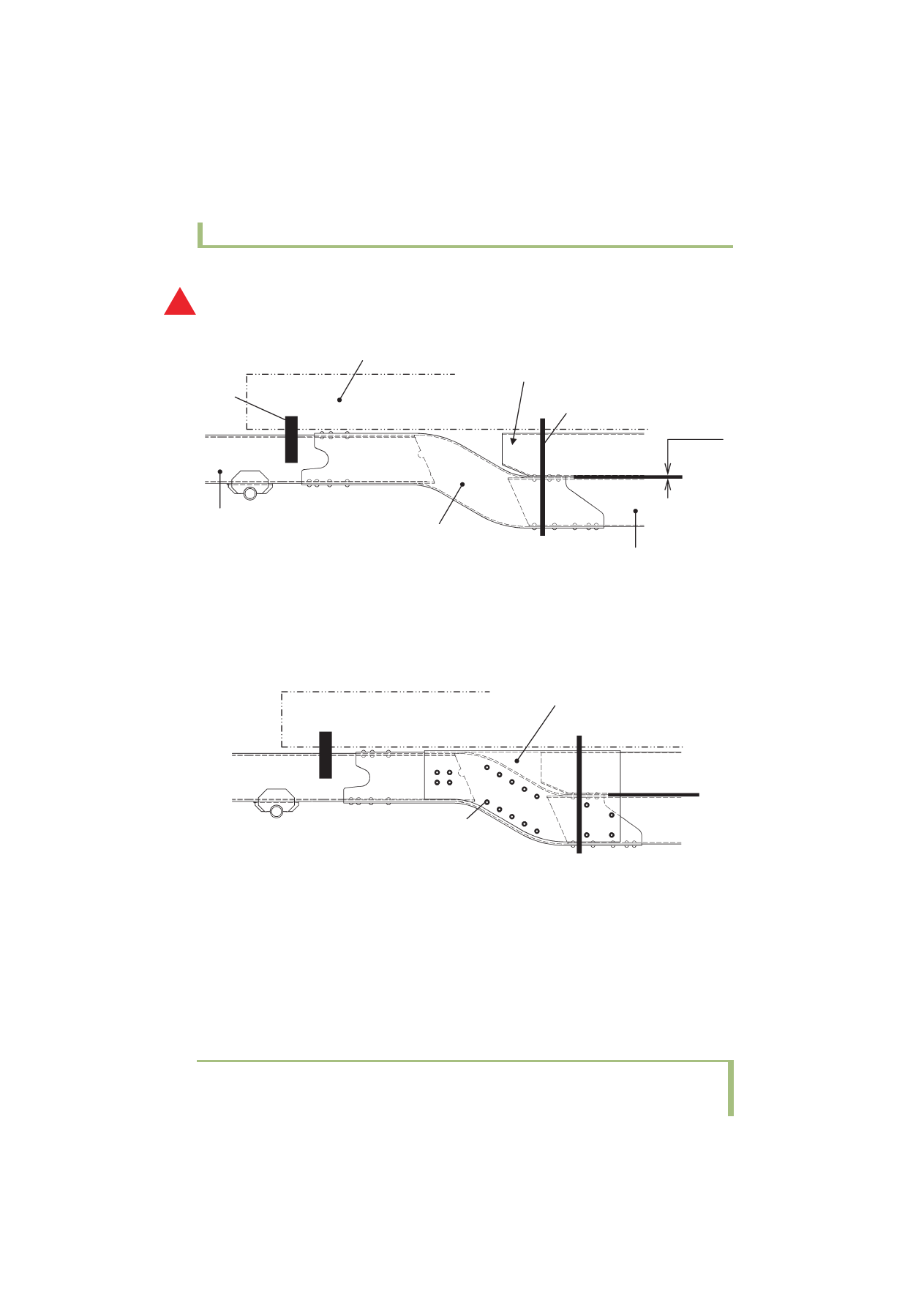
(d) When building a body to the frame of a 4 WD vehicle (FGB model), follow the instructions below.

• In the case of an ordinary body

Join the front end to the FR side rail (1). If this is not possible, join the body to the section where the 
RR side rail and kick-down rail overlap (2).

• In the case of a body that applies concentrated load or excessive force to the frame, or if an excessive 

twisting force may be applied to the frame on rough roads or muddy ground
Add an L-shaped reinforcing member as shown below.
Use M10 bolts (8T) and nuts (6T) with a tightening torque of 60 to 80 N•m {43 to 58 ft.lbs, 6 to 8 
kgf•m} to secure the member together with the existing battery, fuel tank, spare tire hanger, etc.

A

Body

Position the sub-frame as far forward 
as possible.

FR side rail

Kick-down rail

RR side rail

(Spacer)

t6

(1)

(2)

Fig. 5

L-shaped reinforcing member

Bolt

Fig. 6

117

7 Construction of bodies 

7.3 Mounting frame attachment

MITSUBISHI FUSO body/equipment mounting directives for FE, FG  Issue date: 06. 07. 2012

!

 Only print out complete sections from the current version

i

7.3 Mounting frame attachment

Attaching with U-bolts

• Allow sufficient clearance so that the U-bolts for 

tightening sub-frames or main bolsters do not 
come in contact with pipes, hoses, wires and 
harnesses.

• Do not install U-bolts at the taper-cut position of 

the sub-frames or main bolster.

• Place a wooden spacer inside the flange of the side 

rail to avoid bending when tightening the U-bolts.

• Use metal spacers in locations subject to heat, 

such as near the muffler, or other place where it is 
difficult to place wooden spacers.

• Stress in the chassis frame tends to concentrate in 

the areas where the cross member, stiffener and 
gussets are fitted and near the side rail bends. Do 
not install U-bolts and opposed brackets in such 
areas.

Fig. 1

1

50 mm {1.97 in.}

1

Do not install U-bolts in the shaded area.

Fig. 2

2

3

4

5

6

7

1

1

Pipes and other parts

2

Use  double  nuts

3

Main  bolster 

4

Spacer  (Wood)

5

Slip Stopper

6

Spacer (Steel plate or pipe)

7

Make a notch to secure clearance from pipes or tubes.

Installing U-bolts and brackets in the hatched areas is prohibited.

Stiffener

Cross member

Gusset

Do not install within this range.

{3.94}

{3.94}

{3.94}

{1.97}

{1.97}

Unit: mm {in.}

118

7 Construction of bodies 

7.3 Mounting frame attachment

MITSUBISHI FUSO body/equipment mounting directives for FE, FG  Issue date: 06. 07. 2012

!

 Only print out complete sections from the current version

i

Mounting Bracket

When U-bolts cannot be used with a particular body, 
use mounting brackets in those positions to attach it 
to the sub-frame.  Use the following bracket locations 
and installation procedures.

• Attach the mounting brackets to the chassis frame 

with bolts whenever possible.  Be especially careful 
not to damage any pipes, hoses, and wiring 
harnesses attached to or around the frame.

• Do not attach brackets close to the ends of 

crossmembers, gussets or stiffeners.  Brackets 
should be installed at least 200 mm {7.87 in.} away 
from the end of these parts.

<Crew-Cab>

Fig. 1

1

2

3

4

5

6

1

Attached by welding

2

Mounting bracket

3

Use  double  nuts

4

Sub-frame

5

Tighten the bolts and nuts in more than two locations.

6

Chassis frame

Extend the sub frame as far forward as possible.

Locate the headmost fastener (U-bolt or bracket) as 
far forward of the sub frame as possible.

119

7 Construction of bodies 

7.4 Clearance between chassis parts and bodies

MITSUBISHI FUSO body/equipment mounting directives for FE, FG  Issue date: 06. 07. 2012

!

 Only print out complete sections from the current version

i

7.4 Clearance between chassis parts and bodies

The minimum clearance between chassis parts and 
rear body parts must be kept according to the 
following table of minimum clearance standards. 

Part

Minimum Clearance and Notes

1. The Surrounding part of T/M 25 mm {0.98 in.} at surrounding part of transmission except rear part.

2. Clutch and Transmission 

Assembly

Do not install any rear body part in the area of 100 mm {3.94 in.} of the rear 
of the clutch and transmission ass'y, as the ass'y must be moved backward 
in the same inclination line of engine, to pull out the clutch spline shaft, 
when the transmission ass'y is removed from engine for service.

3. Upper part of Transmission

Keep more than 100 mm {3.94 in.} of clearance between the upper surface 
of upper cover and the rear body part if possible, because this clearance is 
used when the transmission upper cover is removed.

4. The surrounding part of the 

Propeller shaft and the Rear 
axle

Min. 25 mm {0.98 in.} of the surrounding part. 

5. The brake hose (which 

connects to the front and 
rear wheel)

Maintain a minimum of 50 mm {1.97 in.} of clearance. This brake hose is 
considered to move when vehicle is driven.

6. The cab back and the 

surrounding part of the 
engine

No equipment must be mounted within 100 mm {3.94 in.} in the cab back, 
except the subframe and the side members. If any equipment inevitably 
comes within this range, install it in such a position which is more than 300 
mm {11.8 in.} from both sides of engine rear part and not over the engine. 
Also take care that all equipment must not stand in the way of air flow which 
is discharged rearward, downward, or sideward from the engine 
compartment. If air flow is restricted, engine compartment temperature will 
excessively rise, resulting in poor engine performance, and fuel pipe and 
electric wiring overheating. Install a protector as shown below on the cab 
back or the front of the fixed rear body as high as possible with regard to 
exhaust so as to block foreign matter, which may come between cab and 
rear body, from high temperature areas of the engine. When a protector is 
installed on the cab back, use the specialized mounting holes provided.

1

Rubber strip

2

Sheet  metal

3

675 mm {26.6 in.}

1

2

3


Content   ..  27  28  29  30   ..