Mitsubishi Canter (FE, FG). Manual - part 28
112
7 Construction of bodies
7.2 Mounting frame
MITSUBISHI FUSO body/equipment mounting directives for FE, FG Issue date: 06. 07. 2012
!
Only print out complete sections from the current version
i
7.2 Mounting frame
All bodies require a mounting frame or a substructure
that assumes the function of a mounting frame to
ensure a reliable connection between the chassis and
the body.
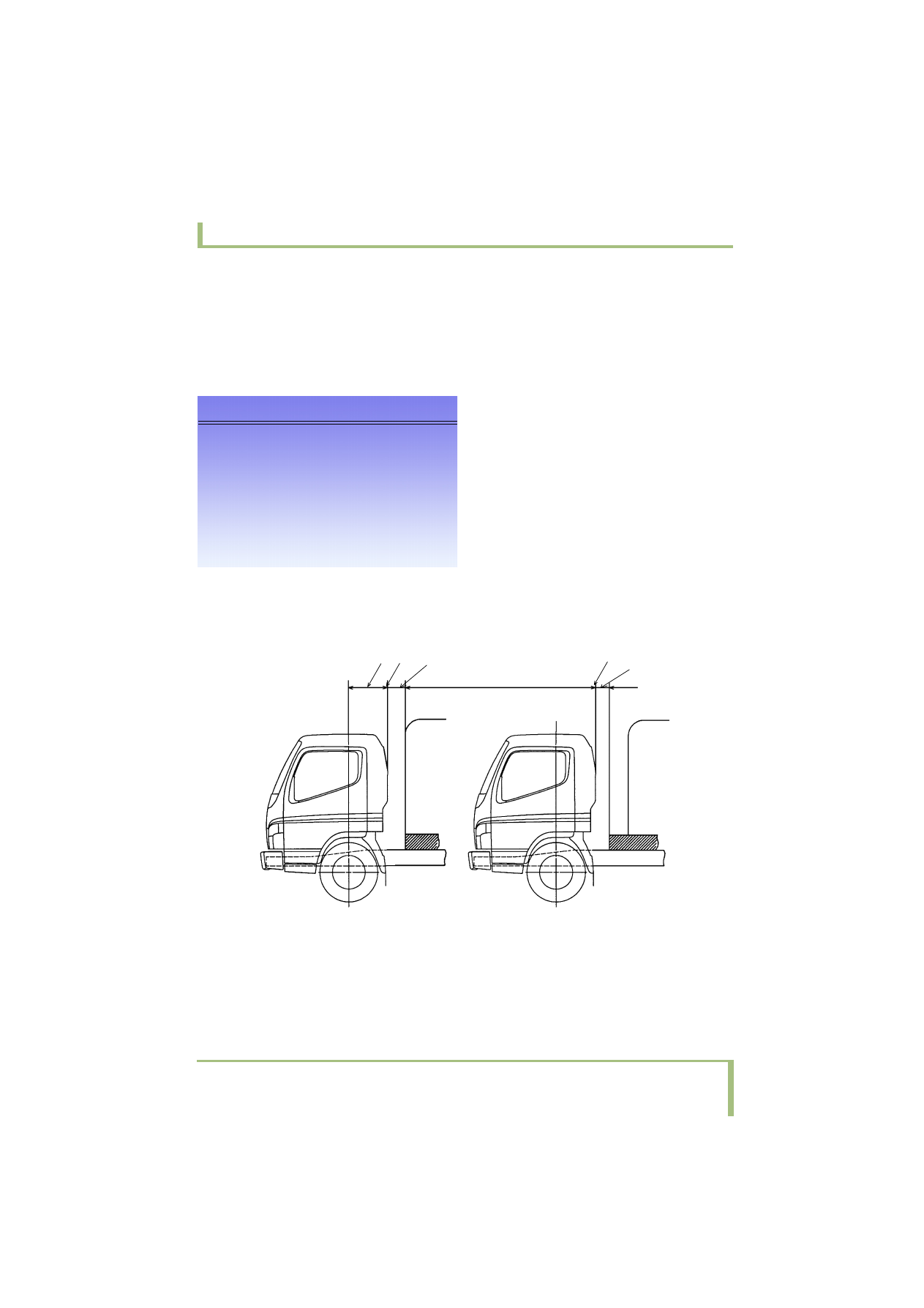
Sub-frame
• Install the sub-frame as shown in Fig. 1 to gradually reduce the stress concentrations in the front end. The
front end of the sub-frame should be installed as close to the rear of the cab as possible. Extend the sub-
frame as far toward the cab as possible when the rear body is installed far from the cab.
!
If more than one body or equipment item is
mounted on the same chassis (e.g. platform and
loading tailgate), the larger of the specified
moments of resistance must be taken to determine
the mounting frame.
1
3
2
3
2
Fig. 1
1
525 mm {20.7 in.}
2
CAB BACK
3
Extend the front end of the sub-frame as far forward as
possible; less than 300 mm {11.81 in.}